00194440-10_SM_X-Series_Customer_en.pdf - 第341页
Settings 5.4.8 Lifting Table Functions Conveyor Settings Service Manual SIPLACE X Series 341 The time will be shown in front of the buttons. ▪ If the cla mping senso r is activated during upw ard travel, a re d LED will …
Settings
Conveyor Settings 5.4.8 Lifting Table Functions
340 Service Manual SIPLACE X Series
5.4.8.1
5.4.8.1 Adjusting the Speed of the Lifting Table (SW601)
Adjusting the Speed of the Lifting Table (SW601)
Applies for SW601. From SW 602 onwards, the lifting table speed can be checked in SITEST.
Parts
▪ Conveyor software [00322132-xx]
▪ Kvaser card
► Use the Kvaser card (1) to connect the service note-
book via the CAN Bus interface to the conveyor con-
trol.
► Start the conveyor software (LP_TSPMenu.exe).
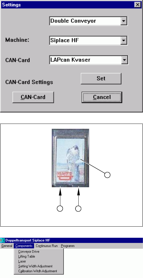
► In the dialog box Settings, select the relevant convey-
or and machine type HF.
► Confirm your choice with Apply.
► Confirm the message Setting applied with OK.
1. Kvaser card
2. Channel 1
3. Channel 2
► Select the channel to be used with the Kvaser card:
channel 1 (2) or channel 2 (3).
► Confirm your setting with Apply.
► Confirm the message Setting applied with OK.
► In the Components menu, select the function Lifting
table. The Lifting table dialog box will open.
Prerequisite:
▪ That the machine is switched on
▪ That the safety covers are closed
▪ That the control unit is switched on
1
3
2
Settings
5.4.8 Lifting Table Functions Conveyor Settings
Service Manual SIPLACE X Series 341
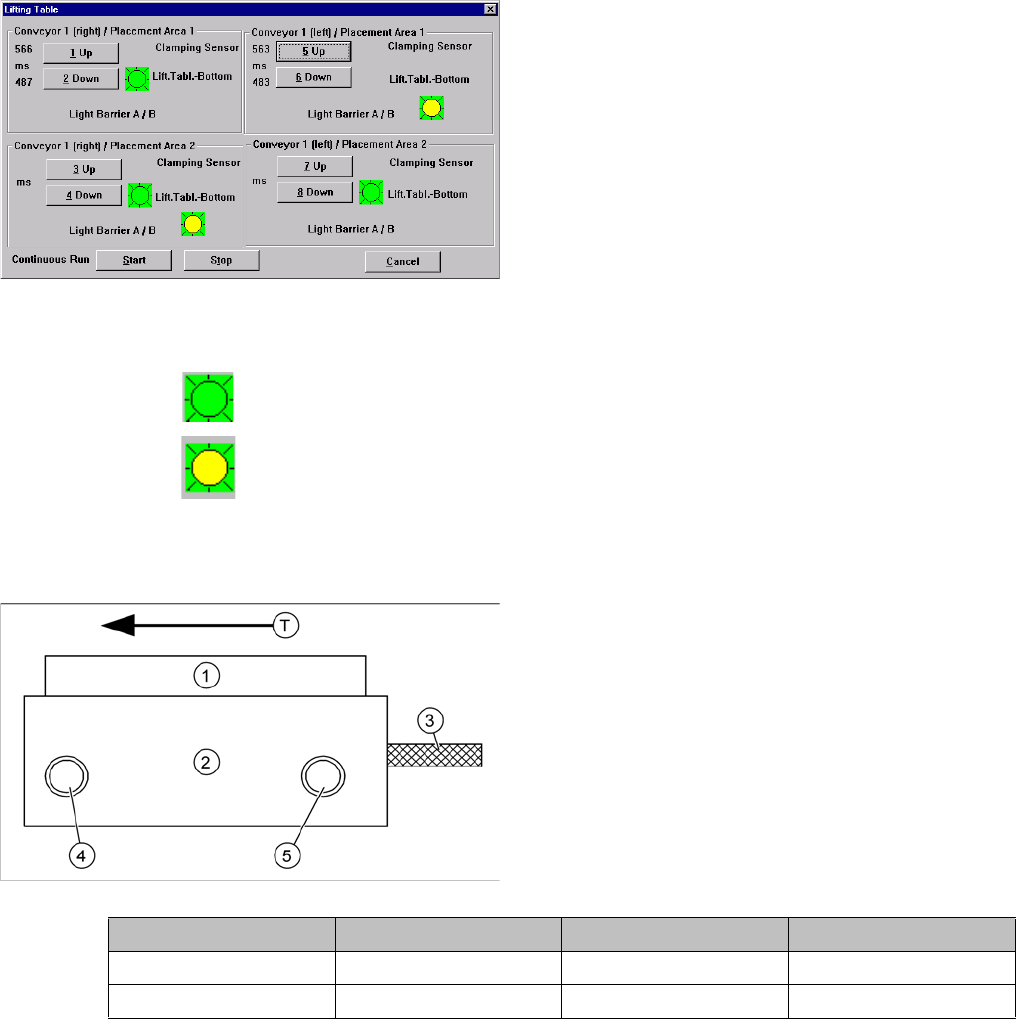
The time will be shown in front of the buttons.
▪ If the clamping sensor is activated during upward travel, a red LED will flash (as pulse).
▪ The icon shows the state "Lifting table down" (LED on the lifting table pneumatic cylinder).
▪ The icon shows the state "Lifting table up" (lifting table measuring system --> number of count-
ing pulses was counted correctly).
Setting times for the lifting table
► Select the lifting table you wish to check or adjust.
Click on the Up and Down buttons.
1. Pneumatic valve
2. Lifting table cylinder
3. Piston rod
4. Adjustment valve – time characteristic for lifting table
down
5. Adjustment valve - time characteristic for lifting table
up
T = transport direction
► Adjust the valves on the lifting table cylinder (5, 6) so
that the following values are achieved:
Move upwards Move downwards Tolerance
Without lifting table plate 540 ms 540 ms +/- 20 ms
With lifting table plate 500 ms 480 ms +/- 20 ms
Settings
Conveyor Settings 5.4.8 Lifting Table Functions
342 Service Manual SIPLACE X Series
5.4.8.2
5.4.8.2 Adjusting the Speed of the Lifting Table (from SW602)
Adjusting the Speed of the Lifting Table (from SW602)
► If the travel times are not inside the tolerance range or if error messages appear during production,
adjust the travel times as follows: adjust the value on the lifting table cylinder so that you get the ap-
propriate values when the lifting table plate is fitted:
⇨ Lifting table up: 500 ms +/-20 ms
(without lifting table plate ~450 +/-20 ms DC / ~360 +/-20 ms SC)
⇨ Lifting table down: 480 ms +/-20 ms
(without lifting table plate ~550 +/-20 ms DC /~600 +/-20 ms SC)
► If malfunctions occur during the downwards movement or if the board is shaken, reduce the lowering
speed accordingly.
Time needed to move lifting table up with lifting table
plate
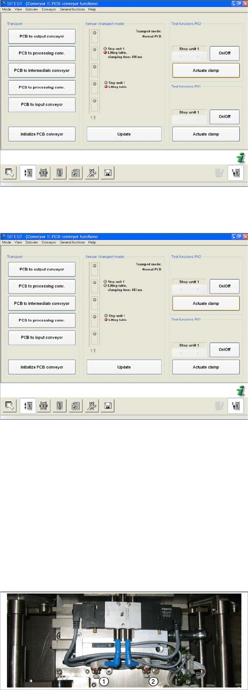
► Switch the machine on and start the SITEST pro-
gram.
► In the PCB conveyor functions menu (see adjacent
diagram) you can see the travel time for the lifting ta-
ble (from SW 602 upwards).
► Select the Actuate clamping button.
Time needed to move lifting table down with lifting table
plate
► The lifting table will be moved up and the travel time
will be displayed (see diagram).
► Select the Actuate clamping button again and the lift-
ing table will move downwards and the travel time for
the downwards movement will be shown.
1. Lower
2. Raise
Turn adjustment valve left:
Reduce of lifting table travel time
Turn adjustment valve right:
Increase lifting table travel time