00194440-10_SM_X-Series_Customer_en.pdf - 第349页
Settings 5.5.2 Component Trolley - Setting the Basic Height Settings on t he Component Trolley Service Manual SIPLACE X Series 349 5.5.2.3 5 . 5 . 2 . 3 A d ju s t in g t h e C o m p o n e n t T r o lle y H e ig h t Adju…
Settings
Settings on the Component Trolley 5.5.2 Component Trolley - Setting the Basic Height
348 Service Manual SIPLACE X Series
5.5.2.2
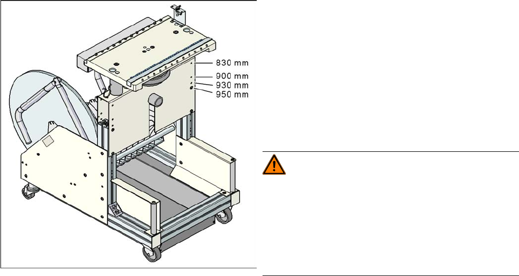
5.5.2.2 Adjusting the Component Trolley to the Board Transport Height
Adjusting the Component Trolley to the Board Transport Height
Component trolley with a PCB conveyor height of
950 mm
▪ Holes drilled for board transport heights 830 -
950 mm in the guidance bars
The component trolley for the S feeder modules can be
easily and quickly adjusted to the following board trans-
port heights:
▪ 830 mm ±15 mm standard height
▪ 900 mm ±15 mm SMEMA height
▪ 930 mm ± 15 mm SMEMA height
▪ 950 mm ±15 mm SMEMA height
WARNING!
The component trolley height may only be set by
SIPLACE technicians or other qualified and officially au-
thorized (certified) personnel.
Observe the applicable accident prevention regulations.
Remove all feeder modules from the changeover table
plate, before you adjust the height of the changeover ta-
ble.
Settings
5.5.2 Component Trolley - Setting the Basic Height Settings on the Component Trolley
Service Manual SIPLACE X Series 349
5.5.2.3
5.5.2.3 Adjusting the Component Trolley Height
Adjusting the Component Trolley Height
Overview
Setting
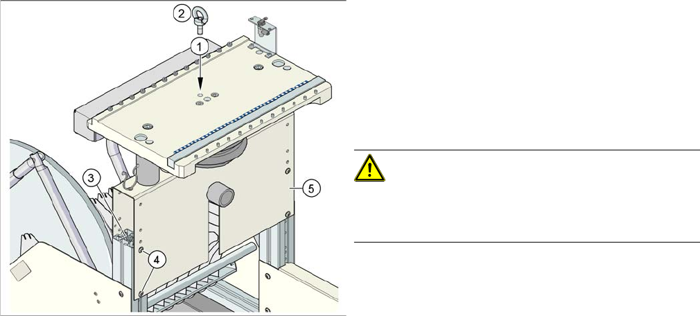
► Remove all the feeder modules from the component trolley.
► Screw the eyebolt into the M12 hole provided (1) on the component trolley table.
► Hook the leverage device into the eyebolt (2).
► Tighten the rope of the leverage device.
► Loosen the 8 hexagon socket-head screws, M6x12 (4).
► Lift or lower the component trolley table to the required height. Make sure that the hole for the re-
quired height in the bridge (5) is level with the top hole in the vertical profile bar (3).
► Fasten the bridge (5) to the vertical profile bar (3) with the eight hexagon socket-head screws M6x12
(4).
► Unscrew the eyebolt from the component trolley table.
Position of eyebolt on component trolley
1. M12 hole drilled for eyebolt
2. Eyebolt DIN 580 M12-St
3. Vertical profile bar
4. Eight pieces hexagon socket-head screw SN 62355,
M6x12
5. Bridge
CAUTION!
Always use the fit-up aid (screwed eyelet) to fix the table
plate, irrespective of whether you want to raise or lower
the component trolley.
Settings
Other Settings 5.6.1 Firmware Download Note
350 Service Manual SIPLACE X Series
5.6
5.6 Other Settings
Other Settings
5.6.1
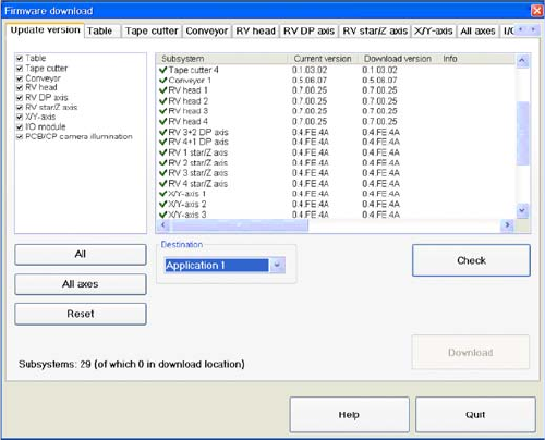
5.6.1 Firmware Download Note
Firmware Download Note
From the following station software versions, the firmware download can be performed to all CAN bus
nodes, via the standard SITEST interface.
▪ 505.04 SP2
▪ 603.01 SP1
▪ 604.01 SP1
5.6.2
5.6.2 Checking the Firmware Function
Checking the Firmware Function
► Select a Target (BIOS/application 1/application 2)
and click on the Check.