00194440-10_SM_X-Series_Customer_en.pdf - 第355页
Settings 5.6.5 Calibration Other Settings Service Manual SIPLACE X Series 355 5.6.5 5 . 6 . 5 C a lib r a t io n Calibration Overview This calibration step first measures the component camera. This determines the relatio…
Settings
Other Settings 5.6.4 Transferring the head specific data
354 Service Manual SIPLACE X Series
5.6.4.2
5.6.4.2 Transferring the Head-Specific Data (from SW701)
Transferring the Head-Specific Data (from SW701)
After changing the head hardware, the new head data
needs to be made available from the head EPROM of the
software.
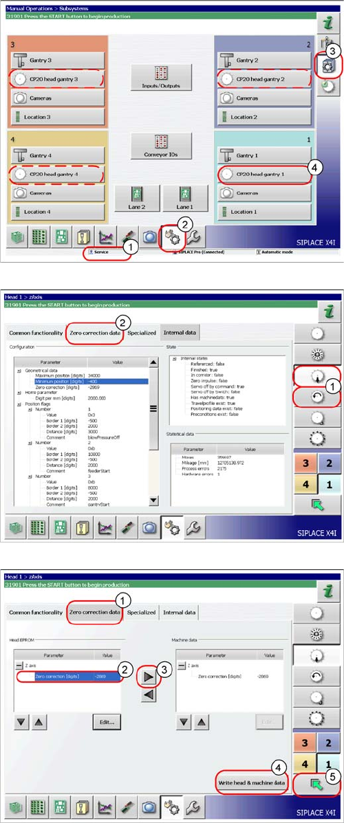
► Switch the machine on.
► Select the operator level Service (Customer) (1).
► Switch over to the menu Check sensors and
functions (2).
► Select the button Check sensors and functions of
specific components (3).
► Select the button CP20 head, gantry x for the relevant
gantry (4).
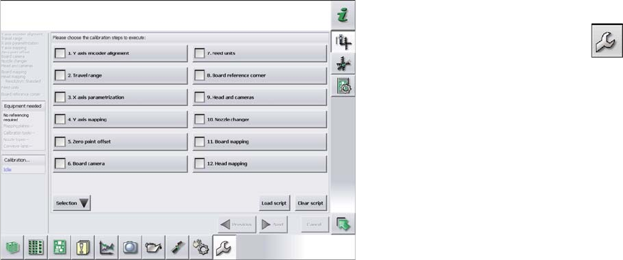
► Select the Z axis/star axis (1).
► Select Zero correction data (2).
This is where the axis data (Z and star axes) can be writ-
ten from the head EPROM to the machine data.
Depending on the head type, you can also write the Z and
star axis data from the machine data to the head
EPROM.
► In the Zero correction data (1) select the line Zero
correction (2).
► Move the value out of the head EPROM and into the
machine data (3).
► Select Write head and machine data (4).
► The arrow button (5) takes you back one menu level.
Settings
5.6.5 Calibration Other Settings
Service Manual SIPLACE X Series 355
5.6.5
5.6.5 Calibration
Calibration
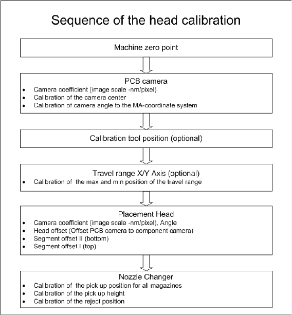
Overview
This calibration step first measures the component camera. This determines the relationship of "camera
pixel size to resolution of machine measuring system (X,Y)", the "camera center point in X and Y direc-
tion" and the "torsion angle of the CCD sensor in the camera". This is following by determining the head
offset and the segment offsets for the top and bottom.
▪ Head offset: the head offset is the distance between the PCB camera and the nozzle (segment 1).
The target is a fixed value (X=0 and Y=-105 mm), to which an offset value (from the head calibration)
is added.
▪ Segment offset top: the top segment offset involves turning the calibration tool in the component
camera in 0, 90, 180 and 270° steps. The value determined is that of the rotating center of the nozzle
tip in relation to the component camera center in the X and Y direction.
▪ Segment offset bottom: the bottom segment offset involves recording and measuring the calibration
tool in the 0, 90, 180 and 270° positions. The value determined is that of the rotating center point of
the nozzle tip when the Z axis is extended in relation to the PCB camera. Segment 1 forms the ref-
erence (X=0, Y=0) to the other segments.
5.6.5.1
5.6.5.1 Calibrating the Heads and Cameras
Calibrating the Heads and Cameras
► Switch over to the operator level Service (Customer).
► Switch over to the Service menu and select Ma-
chine calibration or Automatic calibration (depending
on SW version).
► Select 8. Head and cameras and click on Next.
► On the next page, select the gantries on which the
heads to be calibrated are located and then click on
Next.
► The next step is to check the calibration conditions
(nozzle, calibration tool etc.). Follow the instructions
provided.
After this step, calibration will begin. All required interme-
diate steps (head height etc.) will be performed automat-
ically.
Settings
Other Settings 5.6.5 Calibration
356 Service Manual SIPLACE X Series
5.6.5.2
5.6.5.2 Calibration Procedure
Calibration Procedure
C&P calibration procedure