00194440-10_SM_X-Series_Customer_en.pdf - 第357页
Settings 5.6.6 DIP Switch for Camera Types 25 and 33 Other Settings Service Manual SIPLACE X Series 357 5.6.6 5 . 6 . 6 D I P S w it c h f o r C a m e r a T y p e s 2 5 a n d 3 3 DIP Switch for Cam era Types 25 and 33 Se…
Settings
Other Settings 5.6.5 Calibration
356 Service Manual SIPLACE X Series
5.6.5.2
5.6.5.2 Calibration Procedure
Calibration Procedure
C&P calibration procedure

Settings
5.6.6 DIP Switch for Camera Types 25 and 33 Other Settings
Service Manual SIPLACE X Series 357
5.6.6
5.6.6 DIP Switch for Camera Types 25 and 33
DIP Switch for Camera Types 25 and 33
Setting
► Switch off the machine, disconnect it from the power supply and secure it to prevent unauthorized
reactivation. Observe the instructions in section "1.2 Preparatory Work..." [ ➙ 15].
► Remove the camera upper part and the cover on the lower part, to gain access to the DIP switches.
► Set the DIP switches. (see below)
► Fit all parts by following the above instructions in the reverse order.
DIP switch
Boards with version status 01 and 02 are fitted with a TQ module. In this case, the DIP switching block
is 8 pin.
Boards with version status 03 or higher do not have a TQ module. In this case, the DIP switching block
is 6 pin.
Version state 01 and 02: DIP switch settings (8 pin)
* Not all gantries may be available, depending on the machine type.
Version state 03 and higher: DIP switch settings (6 pin)
* Not all gantries may be available, depending on the machine type.
See also
6.7.1 Vision LED driver VLT 33 [03039244-xx] [ ➙ 381]
S Setting for gantry* Comments
1 2
1OFFOFFBootstrap
2OFFOFFReset
3OFFOFFGantry ID 0
4OFFONGantry ID 1
5OFFOFFTest
6OFFOFFCAN terminator
7ON ON CAN speed: ON: 1 Mbit/s, OFF: 500 KB/s
8 xx xx OFF: FC camera (type 25), ON: IC camera (type 33)
S Setting for gantry* Comments
1 2
1OFFOFFReset
2OFFOFFGantry ID 0
3OFFONGantry ID 1
4 x x x x LED: This switch is delivered with a fixed presetting.
Do not change this setting!
5OFFOFFCAN terminator
6 xx xx OFF: FC camera (type 25), ON: IC camera (type 33)
Settings
Other Settings 5.6.7 Installing the CAN Card Driver
358 Service Manual SIPLACE X Series
5.6.7
5.6.7 Installing the CAN Card Driver
Installing the CAN Card Driver
The new V7.04.14.0 CAN driver needs to be installed manually. This applies to all SW platforms from
60x up to and including SW705.03. From SW705.04 onwards, this is done automatically.
5.6.7.1
5.6.7.1 Checking the Installed Driver Versions
Checking the Installed Driver Versions
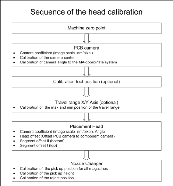
► Switch over to the operating system level at the com-
puter on which the CAN card is installed.
► The task bar shoes a yellow icon (over on the right).
Right-click on this to view more information about the
CAN card.
NOTICE!
The driver is not shown correctly in the Control Panel
Hardware Manager. Make sure you use the icon in the
task bar for this check.
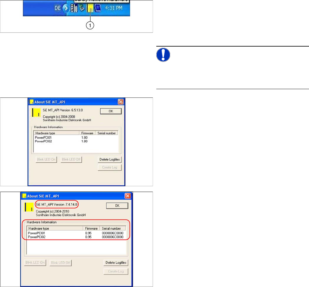
The old CAN card "PowerCAN PCI“ [03052590-xx] is
shown there with the firmware 1.80, the new CAN card
"COM168V2-PCI“ [03079973-xx] is shown with the firm-
ware 0.95.
After replacing the CAN card and successfully installing
the new driver, a version equal to or higher than 7.4.14.0
should be shown.
► If this is not the case, you will need to install the new
driver.