00194440-10_SM_X-Series_Customer_en.pdf - 第36页
Overview of the Modules Electrical System 2.2.6 Subdistributor 36 Service Manual SIPLACE X Series 2.2.6 2 . 2 . 6 S u b d is t r ib u t o r Subdistributor Signals and volta ges can be pro cessed and transmitted to the di…
Overview of the Modules
2.2.5 Main Distributor Electrical System
Service Manual SIPLACE X Series 35
2.2.5.2
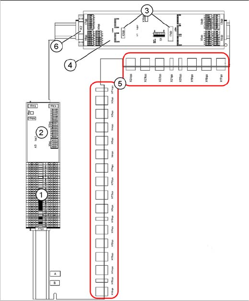
2.2.5.2 Main distributor (X series from Ma. No. B326)
Main distributor (X series from Ma. No. B326)
Main distributor (X-Series from machine number B326,
X4I) [03046225-xx]
1. Terminal strip X1qa (GND, +5 V, +15 V, -15 V,
+24 V, various signals)
2. DC/DC converter for illumination of all cameras
(PCB, component and stationary cameras) in place-
ment area 2
3. Socket for Interface 1-Wire CAT5
4. CAN-Bus I/O module (A1)
5. Connector block (connection X2qa - X6qa, X71qa -
X74qa and X9qa - X24qa)
6. Relay K2 switches the compressed air supply for the
placement heads off (can be configured in the station
software)
Overview of the Modules
Electrical System 2.2.6 Subdistributor
36 Service Manual SIPLACE X Series
2.2.6
2.2.6 Subdistributor
Subdistributor
Signals and voltages can be processed and transmitted to the different system assemblies via the sub-
distributor in sector 4.
2.2.6.1
2.2.6.1 Subdistributor (X series up to Ma. No. B325)
Subdistributor (X series up to Ma. No. B325)
2.2.6.2
2.2.6.2 Subdistributor (X Series from Ma. No. B326)
Subdistributor (X Series from Ma. No. B326)
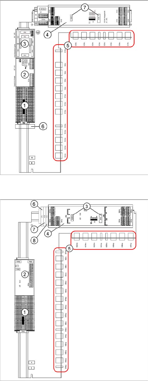
Subdistributor [03010005-xx]
(X-Series up to machine number B325)
1. Terminal strip X1ra (GND,+5 V,+15 V,-
15 V,+24 V,+52 V, various signals)
2. DC/DC distributor for illumination of all cameras
(PCB, component and stationary cameras) in place-
ment area 2
3. Control board for Vision system illumination of sta-
tionary cameras, placement area 1 (future use) (A4)
4. CAN I/O module (A1)
5. Connector block (connection X3ra - X6ra, X71ra-
X74ra, X10ra - X24ra)
6. 8-fold AND connection for safety circuit (A5)
7. Socket for Interface 1-Wire CAT5
Subdistributor [03046226-xx]
(X-Series from machine number B326, X4I)
1. Terminal strip X1ra (GND,+5 V,+15 V,-
15 V,+24 V,+52 V, various signals)
2. DC/DC distributor for illumination of all cameras
(PCB, component and stationary cameras) in place-
ment area 1
3. Socket for Interface 1-Wire CAT5
4. CAN I/O module (A1)
5. Connector block (connection X3ra - X6ra, X71ra-
X74ra, X10ra - X24ra)
6. F1: Fuse for the cover fan
7. K3: Relay for cover fan
8. K1: This relay switches the main valve in the pneu-
matic unit.
Overview of the Modules
2.2.6 Subdistributor Gantries
Service Manual SIPLACE X Series 37
2.3
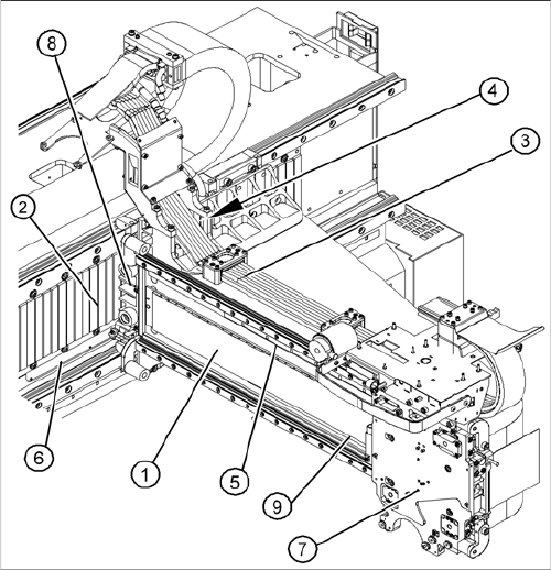
2.3 Gantries
Gantries
Overview
See also
3.3 Gantries [ ➙ 84]
1. X axis
2. Y-Axis
3. Trailing cable
4. Cooling tubes for Y motor cooling system
5. X axis scale
6. Y axis scale
7. X drive (primary)
8. Y drive (primary)
9. Reference proximity switch strip – no function when
using A364 axis card