00194440-10_SM_X-Series_Customer_en.pdf - 第364页
Description of the Circuit Boards Gantry 6.2.1 Head Adapter for TwinHead 364 Service Manua l SIPLACE X Series 6.2 6 . 2 G a n t r y Gantry 6.2.1 6 . 2 . 1 H e a d A d a p t e r f o r T w in H e a d Head Adapter for TwinH…
Description of the Circuit Boards
6.1.1 Inrush Current Limitation Board Transformer (A1) [03066830-xx] Electrics and Control
Service Manual SIPLACE X Series 363
6
6 Description of the Circuit Boards
Description of the Circuit Boards
6.1
6.1 Electrics and Control
Electrics and Control
6.1.1
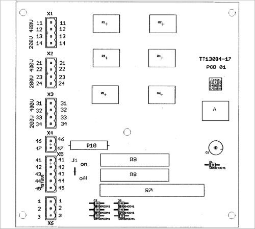
6.1.1 Inrush Current Limitation Board Transformer (A1) [03066830-xx]
Inrush Current Limitation Board Transformer (A1) [03066830-xx]
03066830-01
Jumper J1:
HF/X series: jumper to ON
SX4: jumper to OFF
SX1/SX2: The jumper is not queried here. The jumper
setting is therefore irrelevant.
Description of the Circuit Boards
Gantry 6.2.1 Head Adapter for TwinHead
364 Service Manual SIPLACE X Series
6.2
6.2 Gantry
Gantry
6.2.1
6.2.1 Head Adapter for TwinHead
Head Adapter for TwinHead
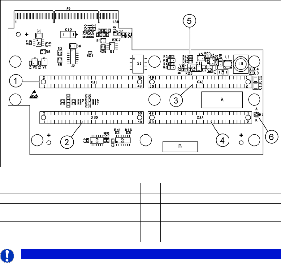
The head adapter board connects the head interface from the bottom side directly. The main boards of
TwinHead segments 1 and 2 are connected directly via two flat ribbon cables, each. In the event of a
head exchange to a C&P, meaning "Head Modularity", this head adapter must also be replaced.
Head adapter for TwinHead
1 Connector Z axis Twin segment 1 4 Connector Z axis Twin segment 2
2 Connector D axis Twin segment 1 5 DIP Switch (without function)
3 Connector D axis Twin segment 2 6 LED C167 = ON TQM Module on the head
interface C500 --> OK
PP1 Boot CAN processor Twin segment 1 PP2 Boot CAN processor Twin segment 2
PP1 Reset CAN processor Twin segment 1 PP2 Reset CAN processor Twin segment 2
NOTICE
Cable sets
The flat ribbon cable sets are different for TwinHead segment 1 and 2.
Description of the Circuit Boards
6.2.2 Head Adapter for C&P20A Gantry
Service Manual SIPLACE X Series 365
6.2.2
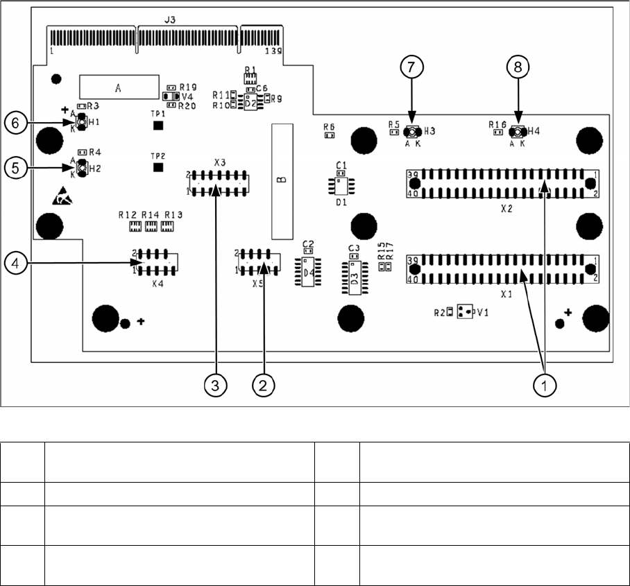
6.2.2 Head Adapter for C&P20A
Head Adapter for C&P20A
Head Adapter for C&P20A
1 X1, X2 connection to intermediate distribu-
tor
5 H2 LED (green) for DP motor 24 V display
2 X5 Z axis track signals 6 H1 LED (red) for 24 V display at C&P20
3 X3 Test connector: Serial Parallel Interface
(SPI) bus
7 H3 LED (green) for component sensor dis-
play
4 X4 star track signals 8 H4 LED (red) for hardware error display at
C&P20A