00194440-10_SM_X-Series_Customer_en.pdf - 第369页
Description of the Circuit Boards 6.2.4 DIP Switch on the Vision Board Gantry Service Manual SIPLACE X Series 369 6.2.4 6 . 2 . 4 D I P S w it c h o n t h e V is io n B o a r d DIP Switch on th e Visi on Board 6.2.4.1 6 …
Description of the Circuit Boards
Gantry 6.2.3 Head Interface C500
368 Service Manual SIPLACE X Series
6.2.3.2
6.2.3.2 DIP Switches on the Head Interface
DIP Switches on the Head Interface
* Not all gantries may be available, depending on the machine type.
S Gantry* Comments
1 2 3 4
1OF
F
ON OF
F
ON P0 - Gantry address switch 1
2OF
F
OF
F
ON ON P1 - Gantry address switch 2
3ONONONONCAN R - CAN terminator (always OFF for
TwinHead)
4OF
F
OF
F
OF
F
OF
F
Boot - CAN processor 16 bit
5OF
F
OF
F
OF
F
OF
F
Reset - CAN processor 16 bit
6OF
F
OF
F
OF
F
OF
F
C0 - CAN Address switch
7OF
F
OF
F
OF
F
OF
F
C1 - CAN Address switch
8OF
F
OF
F
OF
F
OF
F
WPE - Write protect enable at the moment
OFF
CAUTION
Switch 3 (does not apply for X4I machines)
With Head Modularity pay attention: That terminating CAN resistor is set correctly:
Switch 3 is set to ON for C&P heads, to OFF for Twin heads.

Description of the Circuit Boards
6.2.4 DIP Switch on the Vision Board Gantry
Service Manual SIPLACE X Series 369
6.2.4
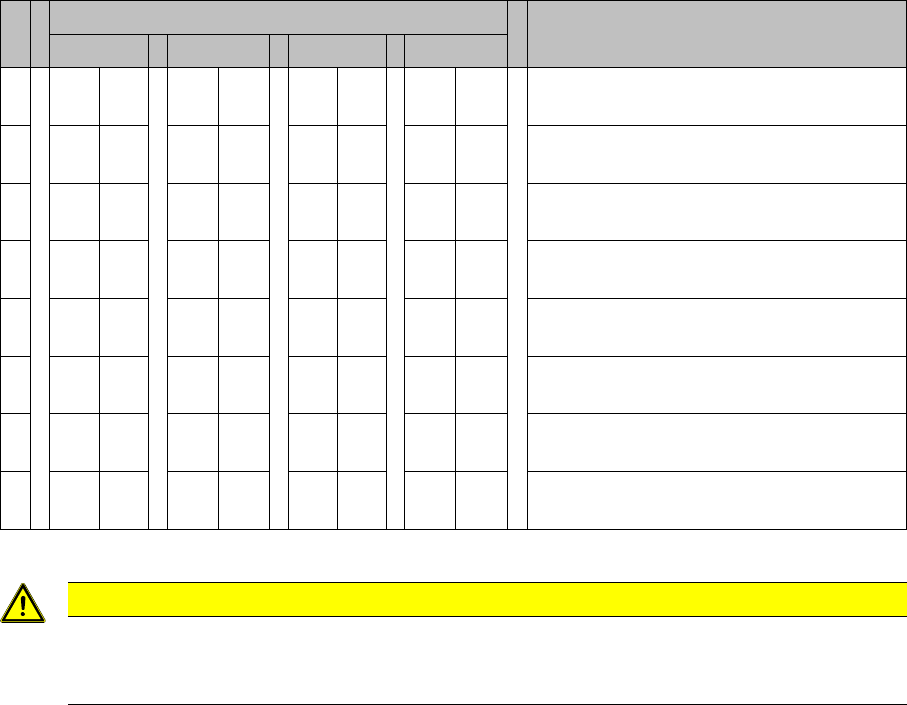
6.2.4 DIP Switch on the Vision Board
DIP Switch on the Vision Board
6.2.4.1
6.2.4.1 DIP Switch on the Vision Board (Digital Version 01)
DIP Switch on the Vision Board (Digital Version 01)
* Not all gantries may be available, depending on the machine type.
6.2.4.2
6.2.4.2 DIP Switch on the Vision Board (Digital Version 02)
DIP Switch on the Vision Board (Digital Version 02)
* Not all gantries may be available, depending on the machine type.
S Gantry* Comments
1 2 3 4
1OF
F
OF
F
OF
F
OF
F
Boot - CAN processor 16 bit on sub board
2OF
F
OF
F
OF
F
OF
F
Reset - CAN processor 16 bit on sub
board
3OF
F
ON OF
F
ON P0 - Gantry address switch 1
4OF
F
OF
F
ON ON P1 - Gantry address switch 2
5OF
F
OF
F
OF
F
OF
F
WPE - Write protect enable, currently OFF
6OF
F
OF
F
OF
F
OF
F
CAN R - Switch terminator CAN bus
7ONONONONTest 1 - CAN 1 MBit/s --> ON
8ONONONONTest 0 - CAN group --> ON
S Gantry* Comments
1 2 3 4
1OF
F
OF
F
OF
F
OF
F
Reset - CAN processor
2OF
F
ON OF
F
ON PID0 address switch 1 -> gantry
3OF
F
OF
F
ON ON PID1 address switch 2 -> gantry
4OF
F
OF
F
OF
F
OF
F
CAN R - switch for the terminal resistor on
the CAN bus
5ONONONONSpeed: ON = 1 Mbit/s, OFF = 500 Kbit/s
6ONONONONCAN ID - for X machine ON
Description of the Circuit Boards
Conveyor 6.3.1 Conveyor Control TSP 301
370 Service Manual SIPLACE X Series
6.3
6.3 Conveyor
Conveyor
6.3.1
6.3.1 Conveyor Control TSP 301
Conveyor Control TSP 301
6.3.1.1
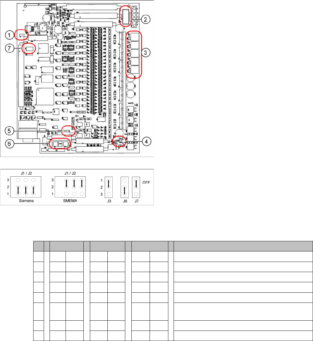
6.3.1.1 Jumper Settings for TSP 301
Jumper Settings for TSP 301
DIL switch S4 at TSP 301
* Switches 1 and 2 set the hardware ID 5 for D4 machines and hardware ID 6 for X4I, X series, HF and
D3.
1. J7 CAN bus 1 terminating resistor
2. F6 Main Fuse TSP 301
3. F1 - F5 Fuses for the conveyor motors
4. J3 interference loop
5. J6 CAN bus 2 terminating resistor (not used)
6. J2, J1 downstream/upstream station
7. S4 DIL switch
Jumper J1, J2 "downstream/upstream station" at TSP
301
▪ J1 upstream station
▪ J2 downstream station
▪ J3 interference loop (EMERGENCY STOP on pro-
ductivity lift also switches the placement machine off)
▪ J6 CAN bus 2 terminating resistor (not used)
▪ J7 CAN bus 1 terminating resistor
S X4I D4 X/D3/HF Comments
1* ON ON ON ON
2* OFF ON OFF ON = SIPLACE D4, OFF: SIPLACE X, HF, D3, X4I
3 OFF OFF OFF OFF= clamping sensor is no longer used
4ONONOFF OFFONON = Quad lane, OFF: Standard conveyor
5 OFF OFF OFF Not in use
6 OFF ON OFF OFF ON OFF: Standard conveyor, ON: Quad
lane (conveyor sides, outer fixed)
7 OFF OFF OFF Not in use
8 OFF OFF OFF Not in use