00194440-10_SM_X-Series_Customer_en.pdf - 第37页
Overview of the Modules 2.2.6 Subdistributor Gantries Service Manual SIPLACE X Series 37 2.3 2 . 3 G a n t r ie s Gantries Overview See also 3.3 Gantrie s [ ➙ 84] 1. X axis 2. Y-Axis 3. Trailing cable 4. Cooling tube…
Overview of the Modules
Electrical System 2.2.6 Subdistributor
36 Service Manual SIPLACE X Series
2.2.6
2.2.6 Subdistributor
Subdistributor
Signals and voltages can be processed and transmitted to the different system assemblies via the sub-
distributor in sector 4.
2.2.6.1
2.2.6.1 Subdistributor (X series up to Ma. No. B325)
Subdistributor (X series up to Ma. No. B325)
2.2.6.2
2.2.6.2 Subdistributor (X Series from Ma. No. B326)
Subdistributor (X Series from Ma. No. B326)
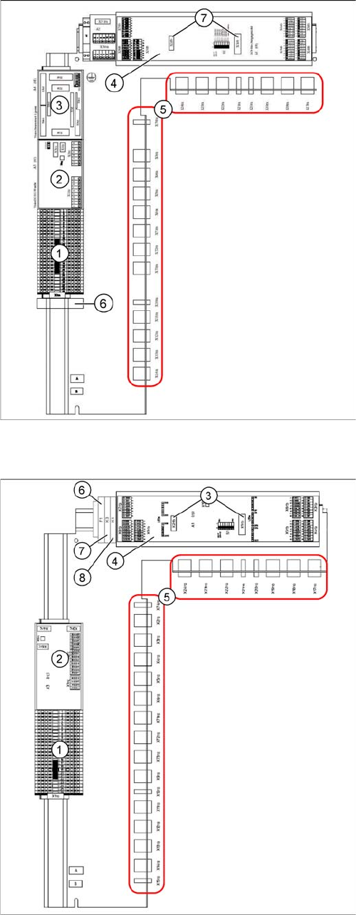
Subdistributor [03010005-xx]
(X-Series up to machine number B325)
1. Terminal strip X1ra (GND,+5 V,+15 V,-
15 V,+24 V,+52 V, various signals)
2. DC/DC distributor for illumination of all cameras
(PCB, component and stationary cameras) in place-
ment area 2
3. Control board for Vision system illumination of sta-
tionary cameras, placement area 1 (future use) (A4)
4. CAN I/O module (A1)
5. Connector block (connection X3ra - X6ra, X71ra-
X74ra, X10ra - X24ra)
6. 8-fold AND connection for safety circuit (A5)
7. Socket for Interface 1-Wire CAT5
Subdistributor [03046226-xx]
(X-Series from machine number B326, X4I)
1. Terminal strip X1ra (GND,+5 V,+15 V,-
15 V,+24 V,+52 V, various signals)
2. DC/DC distributor for illumination of all cameras
(PCB, component and stationary cameras) in place-
ment area 1
3. Socket for Interface 1-Wire CAT5
4. CAN I/O module (A1)
5. Connector block (connection X3ra - X6ra, X71ra-
X74ra, X10ra - X24ra)
6. F1: Fuse for the cover fan
7. K3: Relay for cover fan
8. K1: This relay switches the main valve in the pneu-
matic unit.
Overview of the Modules
2.2.6 Subdistributor Gantries
Service Manual SIPLACE X Series 37
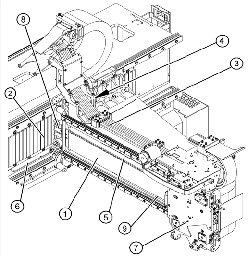
2.3
2.3 Gantries
Gantries
Overview
See also
3.3 Gantries [ ➙ 84]
1. X axis
2. Y-Axis
3. Trailing cable
4. Cooling tubes for Y motor cooling system
5. X axis scale
6. Y axis scale
7. X drive (primary)
8. Y drive (primary)
9. Reference proximity switch strip – no function when
using A364 axis card
Overview of the Modules
Modular PCB Conveyor System 2.4.1 Single Conveyor
38 Service Manual SIPLACE X Series
2.4
2.4 Modular PCB Conveyor System
Modular PCB Conveyor System
The standard machine is equipped as a single PCB conveyor. The dual and quad lane PCB conveyors
are available as options.
2.4.1
2.4.1 Single Conveyor
Single Conveyor
Overview
See also
3.6 Modular PCB Conveyor System [ ➙ 152]
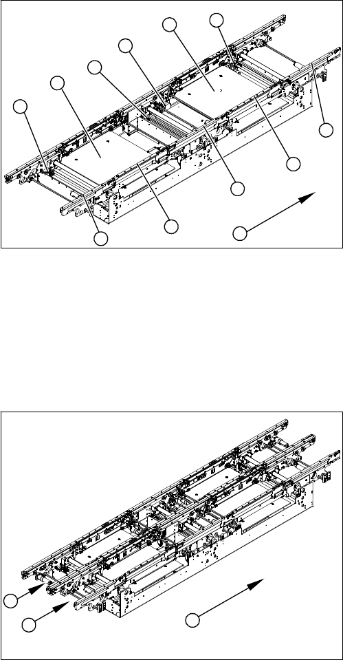
2.4.2
2.4.2 Dual Conveyor System
Dual Conveyor System
Overview
Function Description
The dual conveyor has two conveyor lanes. In the standard version, the fixed conveyor side wall of each
conveyor lane is on the right-hand side.
As in the case of the single conveyor system, the dual conveyor system consists of an input conveyor,
two placement areas, the intermediate conveyor and the output conveyor. The dual conveyor system
has automatic width adjustment and a lifting table to clamp the PCB in place.
1. Input belt
2. Placement area 1
3. Intermediate belt
4. Placement area 2
5. Output belt
6. Lifting table - placement area 1
7. Width adjustment for drive unit
8. Lifting table - placement area 2
9. Width adjustment for adjustment units 1, 2 and 3
10. Transport direction
9
9
1
10
9
8
7
6
5
4
3
2
1. Conveyor lane 1
2. Conveyor lane 2
3. Transport direction
1
3
2