00194440-10_SM_X-Series_Customer_en.pdf - 第376页
Description of the Circuit Boards Cutter 6.4.1 Control Unit on Cutter 376 Service Manua l SIPLACE X Series 6.4 6 . 4 C u t t e r Cutter 6.4.1 6 . 4 . 1 C o n t r o l U n it o n C u t t e r Control Unit on Cutter The jump…
Description of the Circuit Boards
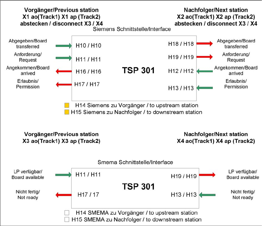
6.3.1 Conveyor Control TSP 301 Conveyor
Service Manual SIPLACE X Series 375
6.3.1.5
6.3.1.5 Siemens/SMEMA TSP 301 Interface Description
Siemens/SMEMA TSP 301 Interface Description
TSP 301 interface
Description of the Circuit Boards
Cutter 6.4.1 Control Unit on Cutter
376 Service Manual SIPLACE X Series
6.4
6.4 Cutter
Cutter
6.4.1
6.4.1 Control Unit on Cutter
Control Unit on Cutter
The jumper for the CAN bus addressing must be set according to the corresponding location in the ma-
chine.
See also
6.4.2 Control Unit on Cutter (CAN Nodes) [ ➙ 377]
NOTICE
Control unit [03006411-xx] is replaced by CAN node module.
This version of the control unit is replaced by the backwards compatible CAN node [03052027-
xx] module.
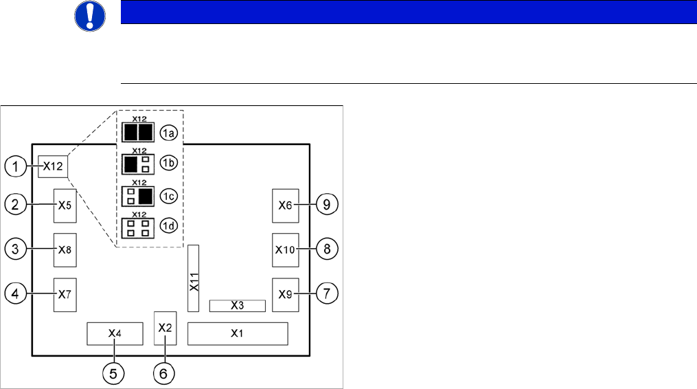
Jumper setting on the tape cutter unit (example of D4/D4i
shown)
1. X12 – Jumper for location encoding for cutter:
1a: gantry 1
1b: gantry 2
1c: gantry 3
1d: gantry 4
2. X5 – Voltage supply to valve (left)
3. X8 – Proximity switch for stroke cylinder out (left)
4. X7 – Proximity switch for stroke cylinder in (left)
5. X4 – CAN bus connection
6. X2 – Voltage supply for cutter +24 V and +5 V
7. X9 – Proximity switch for stroke cylinder in (left)
8. X10 – Proximity switch for stroke cylinder out (right)
9. X6 – Voltage supply to valve (right)
Description of the Circuit Boards
6.4.2 Control Unit on Cutter (CAN Nodes) Cutter
Service Manual SIPLACE X Series 377
6.4.2
6.4.2 Control Unit on Cutter (CAN Nodes)
Control Unit on Cutter (CAN Nodes)
With the CAN node module, a new controller [03052927-xx] has been developed for the SIPLACE X4I,
HF, D3 and X series machines. This controls both the cutter and the nozzle changer of the respective
location. If this control unit is installed in older machines, you will also need to use the relevant CAN bus
address jumper for your machine's installation site.
Description of CAN node NC tape cutter module
This board is backwards compatible to the old tape cutter board. It can be used at X, HF and D series
machines.
The CAN processor decides which functions need to be checked at the individual locations, depending
on the cables connected and the type of DIP switched set.
DIP switch group S3 - overview
1)
Not all gantries may be available, depending on the machine type.
2)
Even if there is no nozzle changer installed and only the tape cutter needs to be controlled, this switch
still needs to be set to OFF for the reject bin query and the reject station.
X series machine with CAN node
The cable of the machine (cable harness machine) has to be by-passed as shown in the list:
*112: Gantry 1: 10/11/12 by-passed
*122: Gantry 2: 11/12 by-passed
*132: Gantry 3: 10/12 by-passed
*142: Gantry 4: not by-passed
CAN node NC tape cutter module
1. X1 – Energy supply with automatic CAN ID
2. X2 – Energy supply, tape cutter +24 V/+5 V
3. X3 – Reject container (nozzles, components)
4. X4 – CAN bus connection
5. X5 – Energy supply to valve (left)
6. X6 – Energy supply to valve (right)
7. X7 – Proximity switch for stroke cylinder out (left)
8. X8 – Proximity switch for stroke cylinder in (left)
9. X9 – Proximity switch for stroke cylinder out (right)
10. X10 – Proximity switch for stroke cylinder in (right)
11. X11– Test connector, tape cutter
12. X12 – Compressed air valve (additional pneumatic
unit for rejecting components)
13. X13 – Nozzle changer, row 1
14. X14 – Nozzle changer, row 2
15. DIP switch group S3 (see below)
DIP
switch
DIP switch meaning
1ON: Setting the CAN ID via DIP switch 2 and 3 – OFF: Cable Select
2 CAN - ID 0
ON: Gantry 1
1)
ON
OFF: Gantry 2
1)
ON
ON: Gantry 3
1)
OFF
OFF: Gantry 4
1)
OFF: Cable se-
lect
3 CAN - ID 1
4
ON: Only tape cutter – OFF: Nozzle changer and tape cutter
2)
5ON: Module in reset-mode – OFF: Module in standard mode