00194440-10_SM_X-Series_Customer_en.pdf - 第38页
Overview of the Modules Modular PCB Conveyor System 2.4.1 Single Conveyor 38 Service Manual SIPLACE X Series 2.4 2 . 4 M o d u la r P C B C o n v e y o r S y s t e m Modular PCB Conveyor System The standard machine is eq…
Overview of the Modules
2.2.6 Subdistributor Gantries
Service Manual SIPLACE X Series 37
2.3
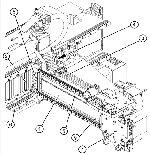
2.3 Gantries
Gantries
Overview
See also
3.3 Gantries [ ➙ 84]
1. X axis
2. Y-Axis
3. Trailing cable
4. Cooling tubes for Y motor cooling system
5. X axis scale
6. Y axis scale
7. X drive (primary)
8. Y drive (primary)
9. Reference proximity switch strip – no function when
using A364 axis card
Overview of the Modules
Modular PCB Conveyor System 2.4.1 Single Conveyor
38 Service Manual SIPLACE X Series
2.4
2.4 Modular PCB Conveyor System
Modular PCB Conveyor System
The standard machine is equipped as a single PCB conveyor. The dual and quad lane PCB conveyors
are available as options.
2.4.1
2.4.1 Single Conveyor
Single Conveyor
Overview
See also
3.6 Modular PCB Conveyor System [ ➙ 152]
2.4.2
2.4.2 Dual Conveyor System
Dual Conveyor System
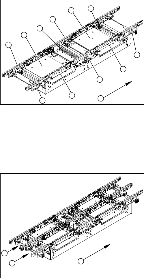
Overview
Function Description
The dual conveyor has two conveyor lanes. In the standard version, the fixed conveyor side wall of each
conveyor lane is on the right-hand side.
As in the case of the single conveyor system, the dual conveyor system consists of an input conveyor,
two placement areas, the intermediate conveyor and the output conveyor. The dual conveyor system
has automatic width adjustment and a lifting table to clamp the PCB in place.
1. Input belt
2. Placement area 1
3. Intermediate belt
4. Placement area 2
5. Output belt
6. Lifting table - placement area 1
7. Width adjustment for drive unit
8. Lifting table - placement area 2
9. Width adjustment for adjustment units 1, 2 and 3
10. Transport direction
9
9
1
10
9
8
7
6
5
4
3
2
1. Conveyor lane 1
2. Conveyor lane 2
3. Transport direction
1
3
2
Overview of the Modules
2.4.3 Quad Lane Conveyor Modular PCB Conveyor System
Service Manual SIPLACE X Series 39
2.4.3
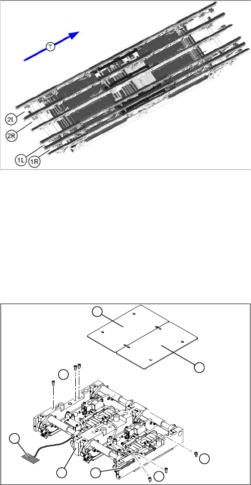
2.4.3 Quad Lane Conveyor
Quad Lane Conveyor
The quad lane conveyor has four lanes. Conveyor lane 1 is divided into lanes 1L and 1R while conveyor
lane 2 is divided into lanes 2L and 2R.
These two double lanes have 20 sonar sensors for PCB recognition. There are also twelve mechanical
stoppers in the input conveyors and in the two placement areas.
2.4.4
2.4.4 Lifting Table
Lifting Table
Overview
Function Description
Depending on the version (single/dual conveyor), one or two independent lifting tables are used in each
placement area. The lifting table is driven indirectly via a pneumatic cylinder, with solenoid valve control.
PCBs of different thicknesses will automatically be compensated for. Movement along the Z axis is
measured at four points on the lifting table plate. A position measuring system determines the lifting path.
The top position of the lifting table is recognized by the position measuring system and the motor current
recognition system. The bottom position of the lifting table is only identified by the position measuring
system. The standard clearance under the PCB is 40 mm (quad lane or X4I: 25 mm). The 94 mm PCB
supports can be used here.
See also
3.6.8 Replacing the Lifting Table Unit [ ➙ 166]
1R: Conveyor lane 1 right
2R: Conveyor lane 2 right
1L: Conveyor lane 1 left
2L: Conveyor lane 2 left
T = Transport direction
1. Lifting table plate
2. Fastening screws for the lifting table unit
3. Lifting table unit
4. Connection cable for lifting table unit
5. Pneumatic connection.
1
2
2
1
5
4
3
2