00194440-10_SM_X-Series_Customer_en.pdf - 第382页
Description of the Circuit Boards Stationary cameras 6.7.2 Vision Control Boar d for IC Camera or F C Camera 382 Service Manua l SIPLACE X Series 6.7.2 6 . 7 . 2 V is io n C o n t r o l B o a r d f o r I C C a m e r a o …
Description of the Circuit Boards
6.7.1 Vision LED driver VLT 33 [03039244-xx] Stationary cameras
Service Manual SIPLACE X Series 381
6.7
6.7 Stationary cameras
Stationary cameras
6.7.1
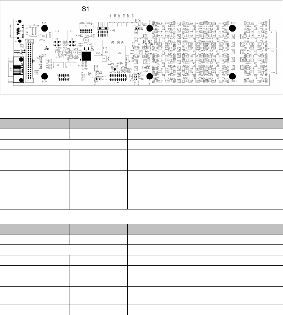
6.7.1 Vision LED driver VLT 33 [03039244-xx]
Vision LED driver VLT 33 [03039244-xx]
This board is part of the stationary camera SST25, SST33 and SST36. The stationary cameras which
can be fitted vary according to the machine type used.
03039244-03
DIP switch S1 for SST25 [03039244-03]
DIP switch S1 for SST33, 36 [03039244-03]
Switch Status Signal name Description
S1.1 OFF VCU_CODE OFF: normal operation, ON: Reset
Gantry 1 Gantry 2 Gantry 3 Gantry 4
S1.2 ON/OFF GANTRY_ID_0 OFF ON OFF ON
S1.3 ON/OFF GANTRY_ID_1 OFF OFF ON ON
S1.4 OFF SMD_LED OFF: standard LED, ON: SMD LED
S1.5 OFF CAN_H OFF: with CAN terminator
ON: without CAN terminator
S1.6 OFF CAN_GROUP OFF: FC camera, ON: IC camera
Switch Status Signal name Description
S1.1 OFF VCU_CODE OFF: normal operation, ON: Reset
Gantry 1 Gantry 2 Gantry 3 Gantry 4
S1.2 ON/OFF GANTRY_ID_0 OFF ON OFF ON
S1.3 ON/OFF GANTRY_ID_1 OFF OFF ON ON
S1.4 OFF SMD_LED OFF: standard LED, ON: SMD LED
S1.5 OFF CAN_H OFF: with CAN terminator
ON: without CAN terminator
S1.6 ON CAN_GROUP ON: IC camera , OFF: FC camera
Description of the Circuit Boards
Stationary cameras 6.7.2 Vision Control Board for IC Camera or FC Camera
382 Service Manual SIPLACE X Series
6.7.2
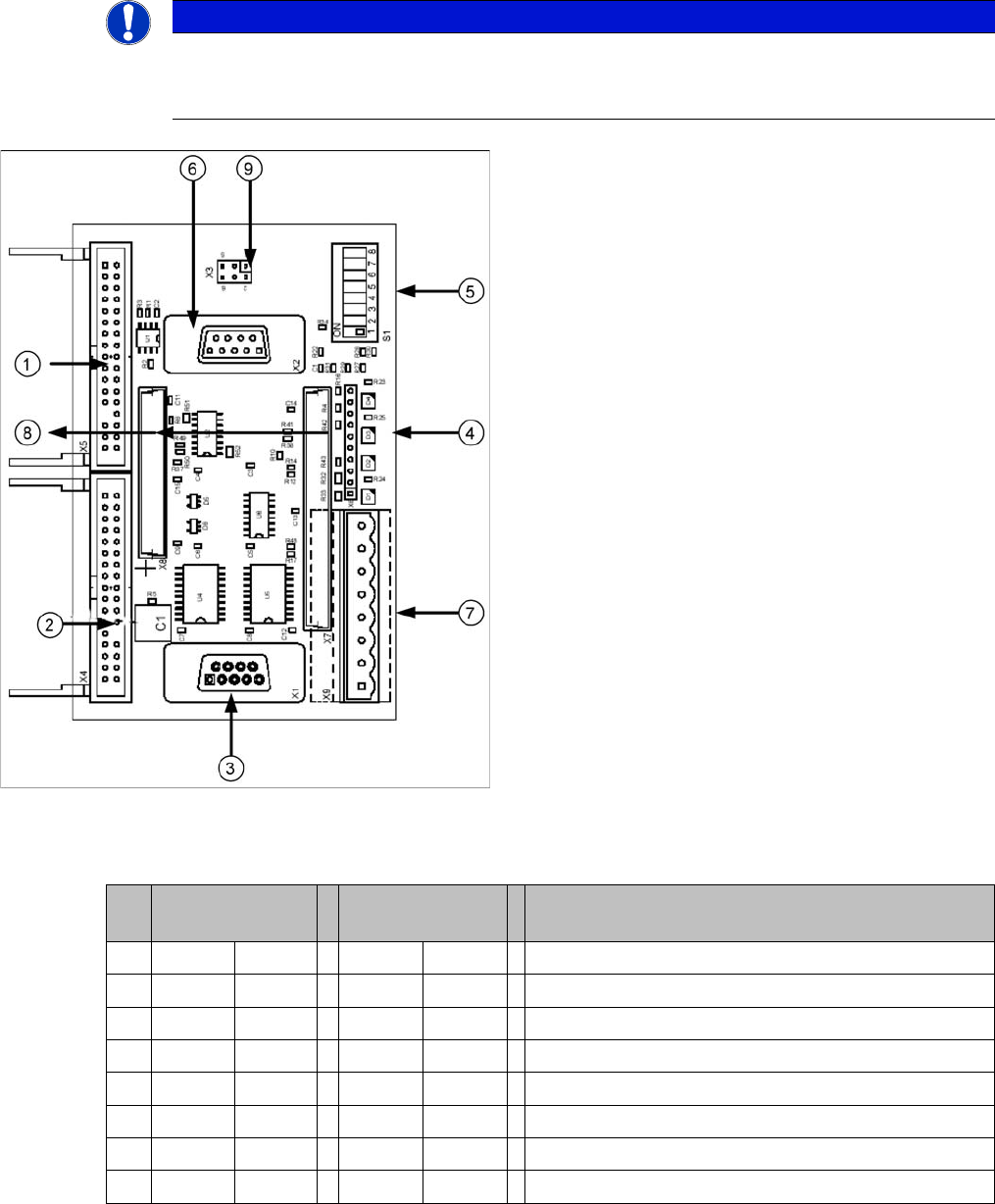
6.7.2 Vision Control Board for IC Camera or FC Camera
Vision Control Board for IC Camera or FC Camera
The vision control board is installed in sector 2 and sector 4 for the stationary cameras.
to 5) DIP switch
NOTICE
Vision control board
When using stationary camera ≧ version 04, the Vision control board is integrated into the
cameras. The Vision control board no longer applies in the sectors.
Vision control board TwinHead IC camera
1. Connector for FC Camera illumination
2. Connector for IC Camera illumination
3. Service connector
4. LEDs (downwards D4 - D1)
+5 V/-15 V/+15 V/+40 V
5. DIP switch
6. Connector CAN Bus
7. Voltage supply for Vision control
Connector for DC/DC converter (sector 2)
DC/DC distributor (sector 4)
8. Connectors for 16 bit CAN Bus processor (TQM mod-
ules)
9. Flash signal (not used for Siplace Vision)
S Sector 2
Main distributor
Sector 4
Subdistributor
Description
1 Off Off CAN terminating resistor - 120 Ohm not set
2 Off Off Reset
3 Off Off Bootstrap
4 Off Off TEST
5 Off ON P1 address switch, gantry ID 1
6ON ONP0 address switch, gantry ID 2
7 Off Off CAN - ID 1
8 Off Off CAN -ID 0
acpage