00194440-10_SM_X-Series_Customer_en.pdf - 第40页
Overview of the Modules Overview of CPP Head 2.4.5 Width Adjustment 40 Service Manual SIPLACE X Series 2.4.5 2 . 4 . 5 W id t h A d ju s t m e n t Width Adjustment Overview Function Description The width is ad justed by …
Overview of the Modules
2.4.3 Quad Lane Conveyor Modular PCB Conveyor System
Service Manual SIPLACE X Series 39
2.4.3
2.4.3 Quad Lane Conveyor
Quad Lane Conveyor
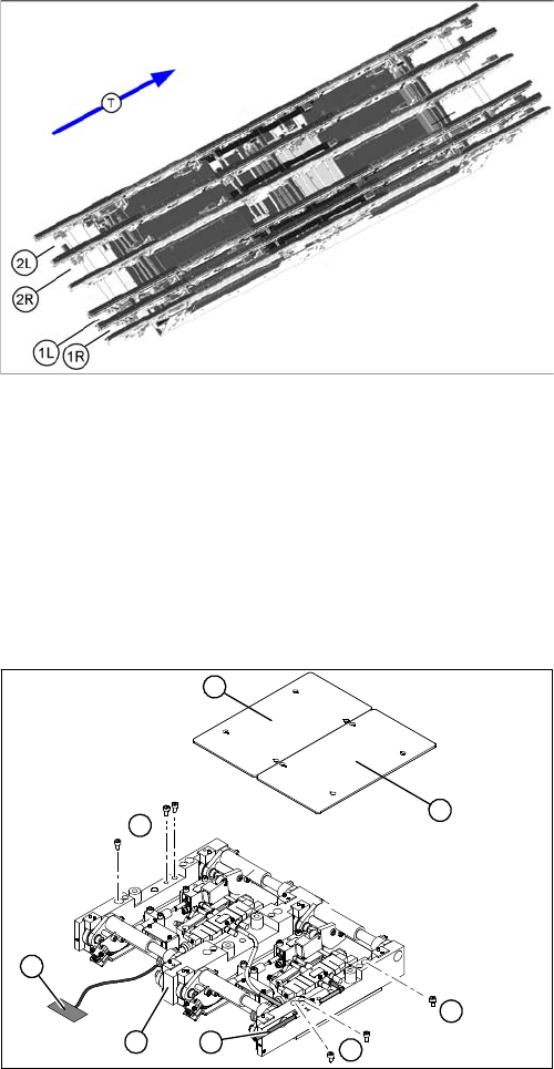
The quad lane conveyor has four lanes. Conveyor lane 1 is divided into lanes 1L and 1R while conveyor
lane 2 is divided into lanes 2L and 2R.
These two double lanes have 20 sonar sensors for PCB recognition. There are also twelve mechanical
stoppers in the input conveyors and in the two placement areas.
2.4.4
2.4.4 Lifting Table
Lifting Table
Overview
Function Description
Depending on the version (single/dual conveyor), one or two independent lifting tables are used in each
placement area. The lifting table is driven indirectly via a pneumatic cylinder, with solenoid valve control.
PCBs of different thicknesses will automatically be compensated for. Movement along the Z axis is
measured at four points on the lifting table plate. A position measuring system determines the lifting path.
The top position of the lifting table is recognized by the position measuring system and the motor current
recognition system. The bottom position of the lifting table is only identified by the position measuring
system. The standard clearance under the PCB is 40 mm (quad lane or X4I: 25 mm). The 94 mm PCB
supports can be used here.
See also
3.6.8 Replacing the Lifting Table Unit [ ➙ 166]
1R: Conveyor lane 1 right
2R: Conveyor lane 2 right
1L: Conveyor lane 1 left
2L: Conveyor lane 2 left
T = Transport direction
1. Lifting table plate
2. Fastening screws for the lifting table unit
3. Lifting table unit
4. Connection cable for lifting table unit
5. Pneumatic connection.
1
2
2
1
5
4
3
2
Overview of the Modules
Overview of CPP Head 2.4.5 Width Adjustment
40 Service Manual SIPLACE X Series
2.4.5
2.4.5 Width Adjustment
Width Adjustment
Overview
Function Description
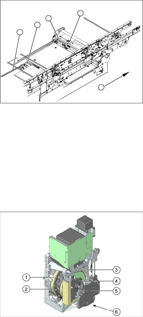
The width is adjusted by means of a motor as programmed. For dual conveyor systems, differing widths
can be set for the two conveyor belts. The width adjustment uses a stepping motor, meaning that the
PCB width can be set independently of other machine components (e.g. the Y gantry).
The PCB width is adjusted via three adjustment units, installed under the input, intermediate and output
conveyors. The stepping motor moves the three adjustment units synchronously through the use of re-
circulating spindles and a toothed belt. The pneumatically operated fixing pins unclamp the conveyor
side edge from the steel strip and connect it to the adjustment unit. After reaching the new PCB width,
both fixing pins move back in. The conveyor side is then clamped again.
2.5
2.5 Overview of CPP Head
Overview of CPP Head
1. Adjustment unit
2. toothed disk with spindle
3. Width adjustment stepping motor
4. Toothed belt for the width adjustment drive
5. Transport direction
1
5
4
3
2
1. Star bearing
2. Segment
3. Front plate
4. Silencer
5. Linear guide for Z drive
6. Component sensor (on the underside of the head)
Overview of the Modules
2.4.5 Width Adjustment C&P20/A/M Head Overview
Service Manual SIPLACE X Series 41
2.6
2.6 C&P20/A/M Head Overview
C&P20/A/M Head Overview
2.7
2.7 C&P6/12 Head - DLM2, DLM3
C&P6/12 Head - DLM2, DLM3
The placement heads C&P6 and C&P12 are available as version DLM2 and DLM3. These versions differ
only in details regarding the star motor, air blast valve and DP drive.
Overview
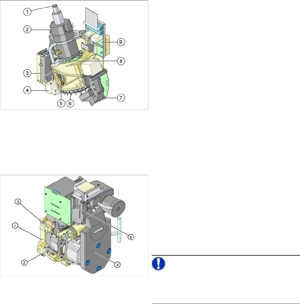
1. Compressed air connection for 20 Venturi nozzles in
the hold circuit
2. Star motor
3. Pressure control valve for pickup and place circuit
4. Component sensor
5. DP drives (20 x)
6. Star with 20 nozzles
7. Component Camera
8. Board for "holding circuit vacuum sensor"
9. Intermediate distributor board
1. Back Part, Complete
2. Star, fitted with twelve or six sleeves
3. Front part, complete
4. Intermediate distributor
5. Component camera
▪ Placement head C&P12 DLM3 [03041228-xx],
C&P12 DLM2 [00367770-xx]
▪ Placement head C&P6 DLM3 [03048341-xx], C&P6
DLM2 [00367020-xx]
NOTICE!
We have not included diagrams of both placement head
types. The structure, function and service work described
apply equally to the C&P6 and the C&P12 head and to
the variants DLM2 and DLM3.