00194440-10_SM_X-Series_Customer_en.pdf - 第42页
Overview of the Modules Overview of TwinHead 2.4.5 Width Adjustment 42 Service Manual SIPLACE X Series 2.8 2 . 8 O v e r v ie w o f T w in H e a d Overview of TwinHead 2.9 2 . 9 C & P 2 0 N o z z le C h a n g e r C&a…
Overview of the Modules
2.4.5 Width Adjustment C&P20/A/M Head Overview
Service Manual SIPLACE X Series 41
2.6
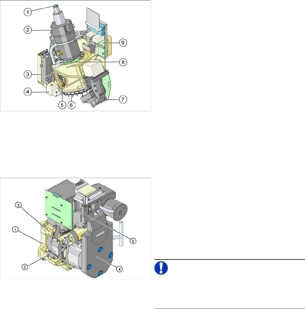
2.6 C&P20/A/M Head Overview
C&P20/A/M Head Overview
2.7
2.7 C&P6/12 Head - DLM2, DLM3
C&P6/12 Head - DLM2, DLM3
The placement heads C&P6 and C&P12 are available as version DLM2 and DLM3. These versions differ
only in details regarding the star motor, air blast valve and DP drive.
Overview
1. Compressed air connection for 20 Venturi nozzles in
the hold circuit
2. Star motor
3. Pressure control valve for pickup and place circuit
4. Component sensor
5. DP drives (20 x)
6. Star with 20 nozzles
7. Component Camera
8. Board for "holding circuit vacuum sensor"
9. Intermediate distributor board
1. Back Part, Complete
2. Star, fitted with twelve or six sleeves
3. Front part, complete
4. Intermediate distributor
5. Component camera
▪ Placement head C&P12 DLM3 [03041228-xx],
C&P12 DLM2 [00367770-xx]
▪ Placement head C&P6 DLM3 [03048341-xx], C&P6
DLM2 [00367020-xx]
NOTICE!
We have not included diagrams of both placement head
types. The structure, function and service work described
apply equally to the C&P6 and the C&P12 head and to
the variants DLM2 and DLM3.
Overview of the Modules
Overview of TwinHead 2.4.5 Width Adjustment
42 Service Manual SIPLACE X Series
2.8
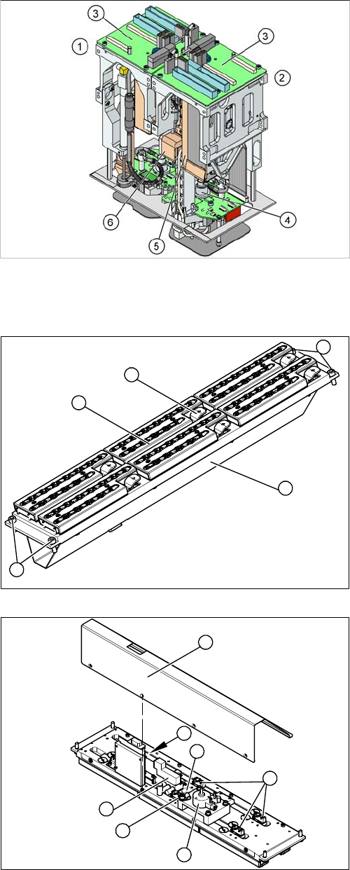
2.8 Overview of TwinHead
Overview of TwinHead
2.9
2.9 C&P20 Nozzle Changer
C&P20 Nozzle Changer
See also
3.5 C&P20 Nozzle Changer [ ➙ 142]
1. Module 1
2. Module 2, rotated by 180° compared to module 1.
3. Main board on module 1 and module 2
4. D Axis
5. Linear motor Z axis
6. Z axis incremental measurement system
1. Cover (covering complete electronic and pneumatic
systems)
2. Toggle (six of them)
3. Nozzle magazine
4. Fastening screws
1. Cover (2 x 4 fastening screws)
2. Control board NC
3. Valve assembly
4. Swivel drive
5. Microswitch (six of them)
6. Green LED 3 mm
4
1
4
3
2
5
1
6
5
4
3
2
Overview of the Modules
2.4.5 Width Adjustment X Series Docking Unit
Service Manual SIPLACE X Series 43
2.10
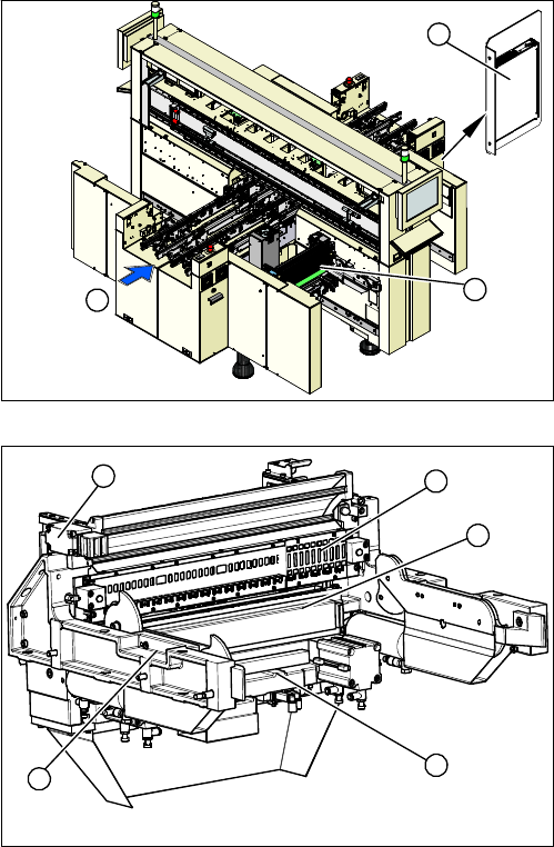
2.10 X Series Docking Unit
X Series Docking Unit
Overview
See also
3.7 X-Series COT Insert [ ➙ 195]
1. Complete component trolley feed device for X Series
[03015680-xx]
2. Voltage supply [03020549-xx]
3. Transport direction
1. Component trolley feed device, complete
2. Safety switch [03019065-xx]
3. Feeder control unit (FCU) [03020068-xx]
4. Feeder unlock device [03011582-xx]
5. Cutter
1
3
2
1
5
4
3
2