00194440-10_SM_X-Series_Customer_en.pdf - 第48页
Overview of the Modules Docking Station for X Series Component Changeover Table 2.4.5 Wi dth Adjustment 48 Service Manual SIPLACE X Series
Overview of the Modules
2.4.5 Width Adjustment Docking Station for X Series Component Changeover Table
Service Manual SIPLACE X Series 47
2.16
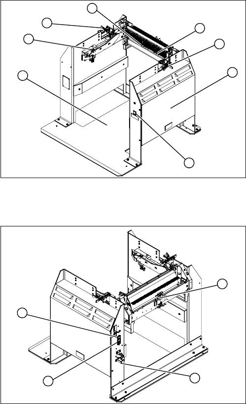
2.16 Docking Station for X Series Component Changeover Table
Docking Station for X Series Component Changeover Table
Overview – view from front
Overview – view from back
1. Docking station – assembly [00116933-xx]
2. Unlocking pushbutton [00334095-xx]
3. Cover (with power pack behind [03025938-XX] and
pressure control valve for locking cylinder)
4. Locking lever [03025104-xx]
5. Feeder unlocking device 40-fold [03011582-XX]
6. Feeder control unit (FCU) [03020068-xx]
7. Short-stroke cylinder for locking unit [03034831-xx]
3
4
1
7
6
5
4
2
1. Control valve [03003489-xx]
2. ON/OFF switch
3. Microfuse [03033387-xx]
4. Pressure control valve for bulkcase feeder and main
connection (5.5 bar)
1
4
3
2
Overview of the Modules
Docking Station for X Series Component Changeover Table 2.4.5 Width Adjustment
48 Service Manual SIPLACE X Series
Service Work
3.1.1 Measuring Voltages at the Power Supply Unit [00354626-xx] Electrics and Control
Service Manual SIPLACE X Series 49
3
3 Service Work
Service Work
3.1
3.1 Electrics and Control
Electrics and Control
Please refer to the circuit diagram folder supplied with your machine for any electrical checks:
▪ Circuit diagram folder SIPLACE X series [00194418-xx] (German)
▪ Circuit diagram folder SIPLACE X series [00194419-xx] (English)
▪ Circuit diagram folder SIPLACE X4I [00195675-xx] (German)
▪ Circuit diagram folder SIPLACE X4I [00195676-xx] (English)
3.1.1
3.1.1 Measuring Voltages at the Power Supply Unit [00354626-xx]
Measuring Voltages at the Power Supply Unit [00354626-xx]
Tools and Equipment Required
▪ Digital voltmeter, class 1, 5
▪ Test cable with test probes or terminals
Preparation
WARNING
Nonobservance of these safety instructions may cause injury to personnel and damage to the
machine!
The service work described in this manual may only be performed by specially trained service
technicians, with appropriate qualifications and expertise.
► Please observe the safety instructions in the Operating Manual for all service work!
CAUTION
Take care not to damage the supply lines!
Make sure that the main power cable and supply cables in the machine are not trapped and
that the insulation is not damaged.
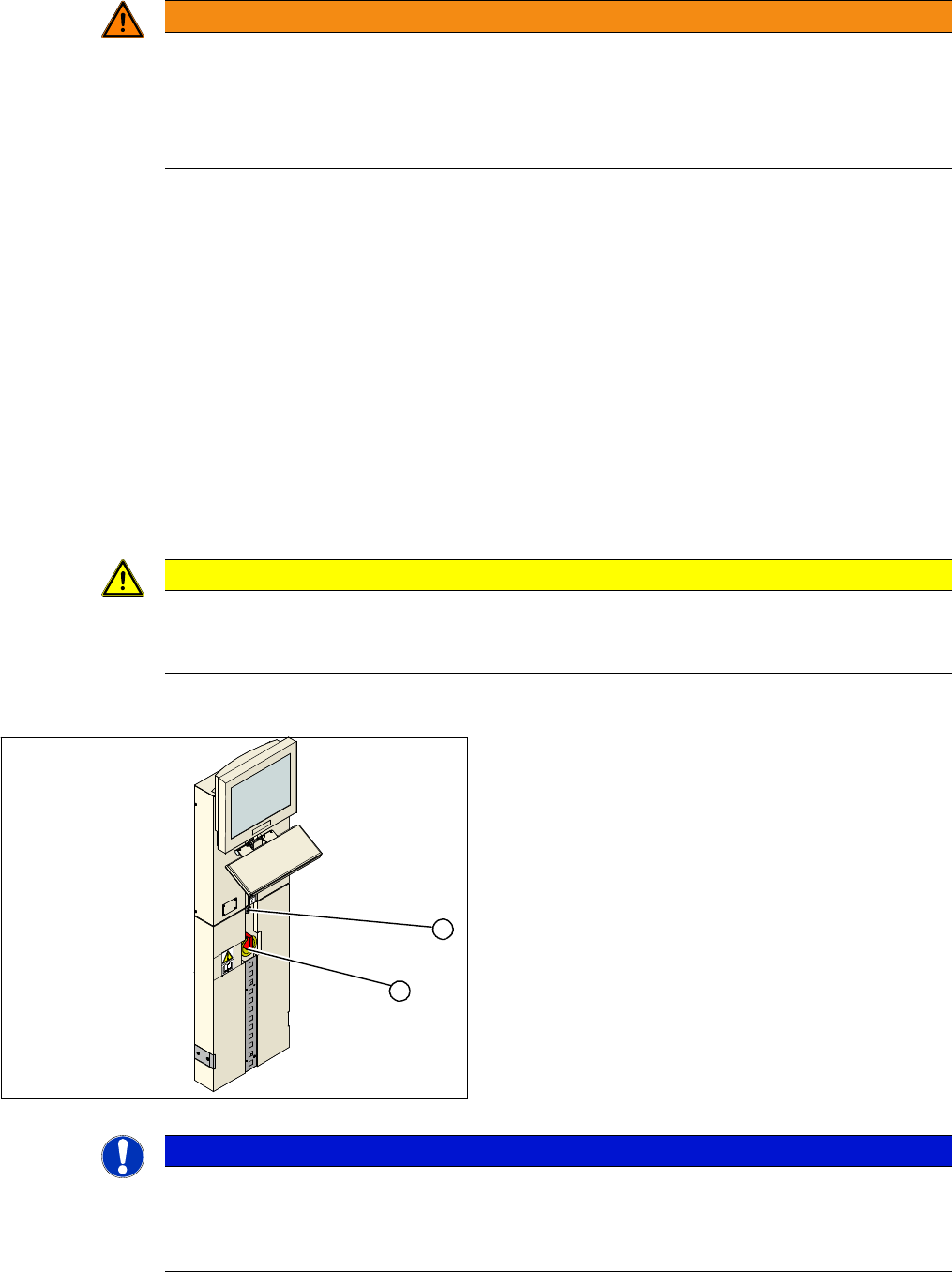
► End all placement operations on the machine.
► Switch the placement system off at the main switch
(1).
► Open the locking mechanism (2) on the power sup-
ply.
► Pull the power supply out towards the front.
► Switch the placement system on at the main switch
(1) and start it up.
► Measure the required voltages. Refer to the circuit di-
agram folder for your machine.
1
2
NOTICE
Inputs, outputs
The inputs to the assemblies are marked with odd numbers, the outputs with even numbers.
The input for the fuses (F1 etc.) is always on the underside of the assembly, while the input for
contactors (K1 etc.) and motor protector switches (Q2 ...) is always on the top.