00194440-10_SM_X-Series_Customer_en.pdf - 第50页
Service Work Electrics and Control 3.1.1 Measuring Voltages at the Power Supp ly Unit [00354626-xx] 50 Service Manual SIPLACE X Series Power supply at the front end 1 Measuring voltages (*) Accord ing to the c usto mer n…
Service Work
3.1.1 Measuring Voltages at the Power Supply Unit [00354626-xx] Electrics and Control
Service Manual SIPLACE X Series 49
3
3 Service Work
Service Work
3.1
3.1 Electrics and Control
Electrics and Control
Please refer to the circuit diagram folder supplied with your machine for any electrical checks:
▪ Circuit diagram folder SIPLACE X series [00194418-xx] (German)
▪ Circuit diagram folder SIPLACE X series [00194419-xx] (English)
▪ Circuit diagram folder SIPLACE X4I [00195675-xx] (German)
▪ Circuit diagram folder SIPLACE X4I [00195676-xx] (English)
3.1.1
3.1.1 Measuring Voltages at the Power Supply Unit [00354626-xx]
Measuring Voltages at the Power Supply Unit [00354626-xx]
Tools and Equipment Required
▪ Digital voltmeter, class 1, 5
▪ Test cable with test probes or terminals
Preparation
WARNING
Nonobservance of these safety instructions may cause injury to personnel and damage to the
machine!
The service work described in this manual may only be performed by specially trained service
technicians, with appropriate qualifications and expertise.
► Please observe the safety instructions in the Operating Manual for all service work!
CAUTION
Take care not to damage the supply lines!
Make sure that the main power cable and supply cables in the machine are not trapped and
that the insulation is not damaged.
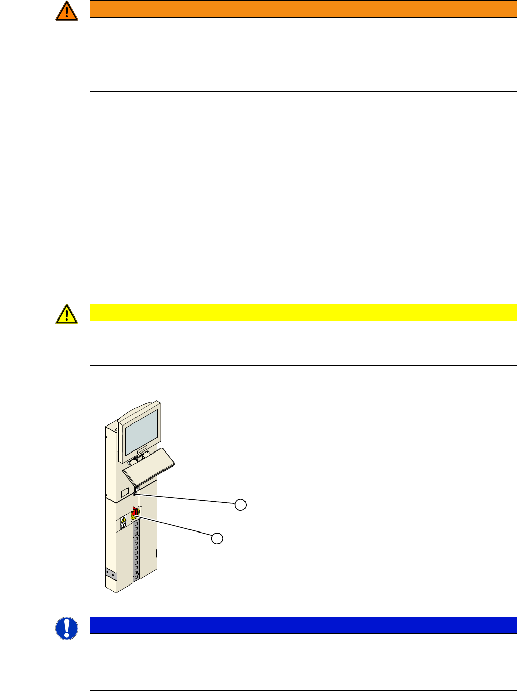
► End all placement operations on the machine.
► Switch the placement system off at the main switch
(1).
► Open the locking mechanism (2) on the power sup-
ply.
► Pull the power supply out towards the front.
► Switch the placement system on at the main switch
(1) and start it up.
► Measure the required voltages. Refer to the circuit di-
agram folder for your machine.
1
2
NOTICE
Inputs, outputs
The inputs to the assemblies are marked with odd numbers, the outputs with even numbers.
The input for the fuses (F1 etc.) is always on the underside of the assembly, while the input for
contactors (K1 etc.) and motor protector switches (Q2 ...) is always on the top.
Service Work
Electrics and Control 3.1.1 Measuring Voltages at the Power Supply Unit [00354626-xx]
50 Service Manual SIPLACE X Series
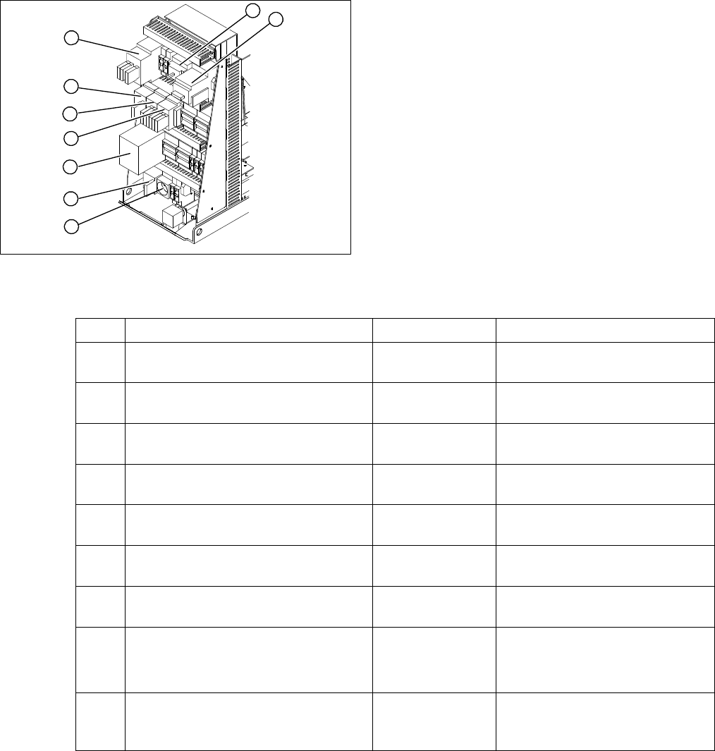
Power supply at the front end 1
Measuring voltages
(*) According to the customer network supply voltage
1. Service socket X102
2. Main switch Q1
3. Motor circuit breaker Q2
4. Main contactor K1
5. Contactor K 2
6. Contactor K 3
7. Contactor K 4
8. Protective contactor combination K6
9. Contactor K 5
1
9
8
7
6
5
4
3
2
Item Designation Contacts Voltage
1 Service socket X102 115 VAC / 220 VAC /
230 VAC 240 VAC (*)
2 Main switch Q1 1, 3, 5 and
2, 4, 6
3 x 204 VAC / 3 x 380 VAC
3 x 400 VAC / 3 x 415 VAC (*)
3 Motor circuit breaker Q2 1, 3, 5 and
2, 4, 6
3 x 204 VAC / 3 x 380 VAC
3 x 400 VAC / 3 x 415 VAC (*)
4 Contactor K 1 1, 3, 5 and
2, 4, 6
3 x 204 VAC / 3 x 380 VAC
3 x 400 VAC / 3 x 415 VAC (*)
5 Contactor K 2 1, 3, 5 and
2, 4, 6
3 x 177 VAC
6 Contactor K 3 1, 3, 5 and
2, 4, 6
3 x 177 VAC
7 Contactor K 4 1, 3, 5 and
2, 4, 6
3 x 177 VAC
8 Protective contactor combination K6 L+, X1,X3, X5
13, 33
23
24 V DC against ground
24 V DC against ground
32 V DC against ground
9 Contactor K 5 A1 (+) to A2 (-)
1, 3, 7
2, 4, 8
24 VDC
24 V DC against ground
24 V DC against ground
Service Work
3.1.1 Measuring Voltages at the Power Supply Unit [00354626-xx] Electrics and Control
Service Manual SIPLACE X Series 51
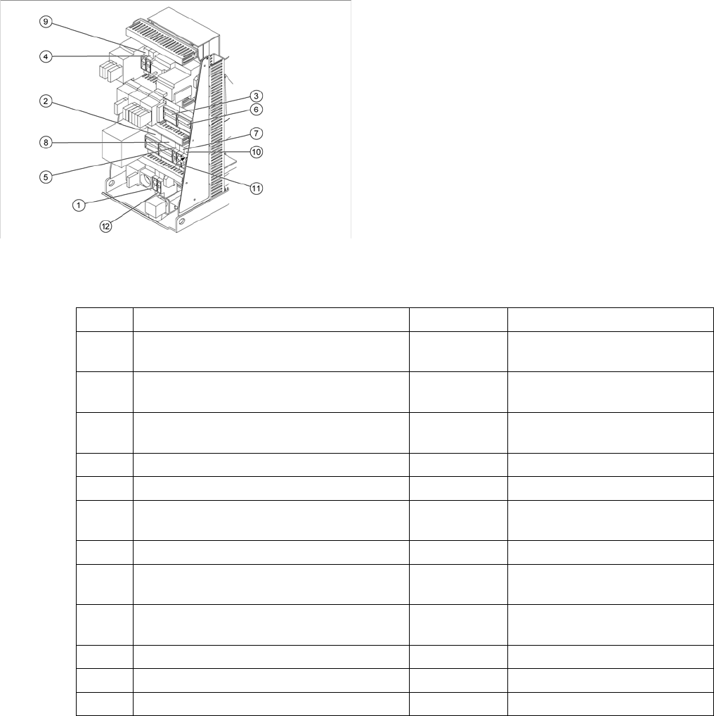
Power supply at the front end 2
Measuring voltages
(*) According to the customer network supply voltage
1. Fuse F1
2. Fuse F2
3. Fuse F4
4. Fuse F5
5. Fuse F6
6. Fuse F7
7. Fuse F8
8. Fuse F10
9. Fuse F11
10. Fuse F12
11. Fuse F13
12. Fuse F14
Item Designation Contacts Voltage
1 Fuse F1 for service socket (6A) 1, 2 115 VAC / 220 VAC
230 VAC / 240 VAC (*)
2 Fuse F2 Component changeover table
(32A)
1, 3, 5 and
2, 4, 6
3 x 36 VAC
3 Fuse F4 X/Y axis (32A) 1, 3, 5 and
2, 4, 6
3 x 177 VAC
4 Fuse F5 Star axis (10A) 1, 2 145 V DC against ground
5 Fuse F6 Z and DP axis, DP for C&P20 (10) 1, 2 39 V DC against ground
6 Fuse F7 Secondary circuit (6A) 1, 3, 5 and
2, 4, 6
3 x 230 VAC
7 Fuse F8 PCB conveyor (6A) 1, 2 33 V DC against ground
8 Fuse F10 Rectifiers U7 and U70 (16A) 1, 3, 5 and
2, 4, 6
3 x 39 VAC
9 Fuse F11 Inrush current limitation board
(1A)
1, 2 33.6 V DC against ground
10 Fuse F12 Illumination (6A) 1, 2 52 V DC against ground
11 Fuse F13 Monitor (3A) 1, 2 26 V DC against ground
12 Fuse F14 Fan Y motor (6A) 1, 2 26 V DC against ground