00194440-10_SM_X-Series_Customer_en.pdf - 第56页
Service Work Electrics and Control 3.1.3 Replacing the Motor Circuit Breaker with Motor Protection Tripping Unit 56 Service Manual SIPLACE X Series Installation Motor protection tr ipping unit settings ► Check t he trigg…
Service Work
3.1.3 Replacing the Motor Circuit Breaker with Motor Protection Tripping Unit Electrics and Control
Service Manual SIPLACE X Series 55
Overview
Removal
► Switch off the machine, disconnect it from the power supply and secure it to prevent unauthorized
reactivation. Observe the instructions in section "1.2 Preparatory Work..." [ ➙ 15].
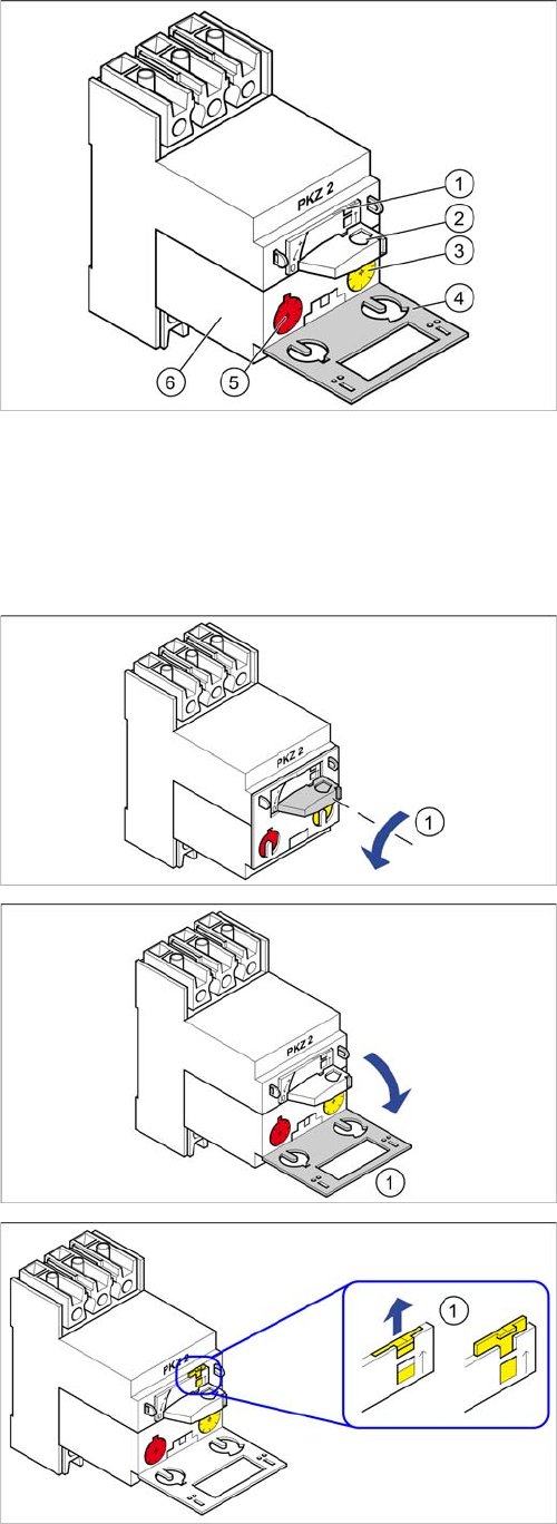
Motor circuit breaker
1. Locking tab
2. Rotary switch
3. Trigger threshold for overcurrent (yellow setting disk)
4. Protective flap
5. Trigger threshold for short-circuit current (red setting
disk)
6. Motor protection tripping unit
► Turn the switch (1) anticlockwise to the position "0"
► Open the protective flap (1).
► Use a screwdriver to push the yellow locking tab (1)
upwards.
Service Work
Electrics and Control 3.1.3 Replacing the Motor Circuit Breaker with Motor Protection Tripping Unit
56 Service Manual SIPLACE X Series
Installation
Motor protection tripping unit settings
► Check the trigger threshold for overcurrent (yellow setting disk)
► Check the trigger threshold for short-circuit current (red setting disk)
► Set the motor protection tripping unit
► Push the yellow locking tab downwards
► Close the gray protective flap.
► Turn the rotary switch clockwise as far as the stopper.
3.1.3.3
3.1.3.3 Replacing the Motor Circuit Breaker PKE32/XTU-32 [03098183-xx]
Replacing the Motor Circuit Breaker PKE32/XTU-32 [03098183-xx]
Missing Axis Support – TI2013-07D10
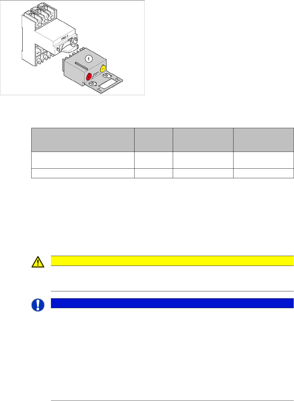
► Pull the motor protection tripping unit (1) out.
Motor protec-
tion tripping
unit
Yellow setting disk for
overcurent trigger
threshold
Red setting disk for
short-circuit current
trigger threshold
X series/SX4/DX4 for 3x110V~ +/-5%
(US version)
ZM-32-PKZ2 24 A 375 A
X series/SX4/DX4 for 3x230V~ +/-5% ZM-16-PKZ2 16 A 200 A
CAUTION
New version
Do not confuse this version of the motor circuit breaker with the old one. Pay particular attention
to the settings.
NOTICE
Missing axis support
The machine is switched on with the help of an extension axis via the motor circuit breaker.
When inserting the door coupling handle onto the extension axis of the motor circuit breaker,
the axis could move into a slanted position. In this case, high traverse forces will be exerted
against the axis coupling of the motor circuit breaker, which could then break. This would then
make it impossible to switch the machine on or off.
Some machines do not have this additional axis support on the motor circuit breaker. This sup-
port is used to limit the slant of the extension axis and therefore to reduce the traverse forces
against the axis coupling.
► This axis support can be retrofitted. For details, read the technical information "Retrofit
Guide Axis Support Motor Circuit Breaker PKE32/XTU-32 Assembly 3p. (Main Switch)"
[DE: TI2013-07D10] [EN: TI2013-07E10].
Service Work
3.1.3 Replacing the Motor Circuit Breaker with Motor Protection Tripping Unit Electrics and Control
Service Manual SIPLACE X Series 57
Parts, equipment and tools
▪ Motor circuit breaker PKE32/XTU-32 assembly 3p. [03098183-xx]
The motor circuit breaker is supplied together with the tripping unit.
▪ Technical information "Retrofit Guide Axis Support Motor Circuit Breaker PKE32/XTU-32 Assembly
3p. (Main Switch)" [DE: TI2013-07D10] [EN: TI2013-07E10].
Overview
Removal
► Switch off the machine, disconnect it from the power supply and secure it to prevent unauthorized
reactivation. Observe the instructions in section "1.2 Preparatory Work..." [ ➙ 15].
► Unplug all connections to the motor circuit-breaker. You may want to mark their positions, to make
clear assignment easier later on.
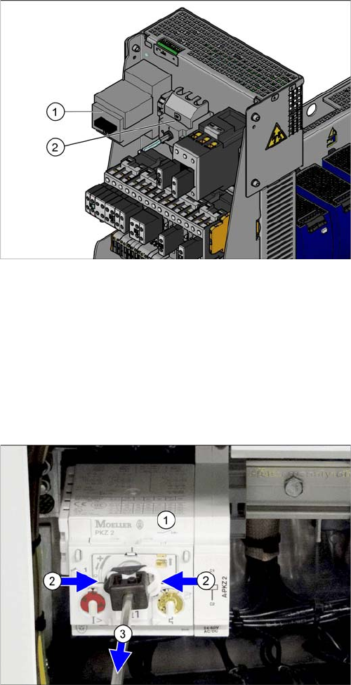
Motor circuit breaker and main switch (using example of
US version)
1. Motor circuit breaker
2. Main switch (US version only)
In non-US versions, the motor circuit breaker also serves
as the main switch.
► Remove the shaft which connects the motor circuit
breaker (1) to the outer main switch handle. To do
this, press the white plastic clips together (2) and pull
off the shaft(3).
► Loosen the latch for the motor circuit breaker on the
rail and remove the motor circuit breaker. You may
need to read the manufacturer's instructions provid-
ed.