00194440-10_SM_X-Series_Customer_en.pdf - 第58页
Service Work Electrics and Control 3.1.4 Replac ing the Axis Unit with Adapter Cable (X, D Series) 58 Service Manual SIPLACE X Series Installation ► Follow the removal in structions in reverse order for installati o n. A…
Service Work
3.1.3 Replacing the Motor Circuit Breaker with Motor Protection Tripping Unit Electrics and Control
Service Manual SIPLACE X Series 57
Parts, equipment and tools
▪ Motor circuit breaker PKE32/XTU-32 assembly 3p. [03098183-xx]
The motor circuit breaker is supplied together with the tripping unit.
▪ Technical information "Retrofit Guide Axis Support Motor Circuit Breaker PKE32/XTU-32 Assembly
3p. (Main Switch)" [DE: TI2013-07D10] [EN: TI2013-07E10].
Overview
Removal
► Switch off the machine, disconnect it from the power supply and secure it to prevent unauthorized
reactivation. Observe the instructions in section "1.2 Preparatory Work..." [ ➙ 15].
► Unplug all connections to the motor circuit-breaker. You may want to mark their positions, to make
clear assignment easier later on.
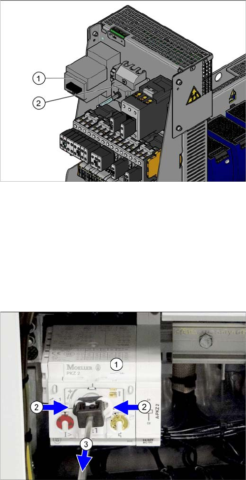
Motor circuit breaker and main switch (using example of
US version)
1. Motor circuit breaker
2. Main switch (US version only)
In non-US versions, the motor circuit breaker also serves
as the main switch.
► Remove the shaft which connects the motor circuit
breaker (1) to the outer main switch handle. To do
this, press the white plastic clips together (2) and pull
off the shaft(3).
► Loosen the latch for the motor circuit breaker on the
rail and remove the motor circuit breaker. You may
need to read the manufacturer's instructions provid-
ed.
Service Work
Electrics and Control 3.1.4 Replacing the Axis Unit with Adapter Cable (X, D Series)
58 Service Manual SIPLACE X Series
Installation
► Follow the removal instructions in reverse order for installation. Also observe the following instruc-
tions:
Settings
► Set the trigger threshold for the nominal current (left setting disk).
► Set the trigger threshold for the overload class (right setting disk).
3.1.4
3.1.4 Replacing the Axis Unit with Adapter Cable (X, D Series)
Replacing the Axis Unit with Adapter Cable (X, D Series)
Parts, equipment and tools
▪ Axis unit A364 replacement kit [03050365S02]
This contains the following parts:
– Axis unit A364 [03050365-02]
– Adapter cable harness for axis unit [03050590-01]
– 2 DIN912-M3 x 6-A2-70 screws [00201463-xx]
CAUTION
Installation instructions
► Please observe the instructions for correct assembly in the technical information "Retrofit
Guide Axis Support Motor Circuit Breaker PKE32/XTU-32 Assembly 3p. (Main Switch)"
[DE: TI2013-07D10] [EN: TI2013-07E10].
► Remove the shaft from the old switch and fit it on the new switch.
► Set the nominal current and overcurrent (see below)
Motor protection tripping unit
PKE-ZTU-32
Left setting disk
for nominal current
Right setting disk
for overcurrent class
SX1/SX2
3x380V - 3x 415V 8 A 5
3x200V - 3x 230V 13.5 A 5
X series S, SX4/DX4
3x380V to 3x415V
One vacuum pump or none
8 A 5
3x200V - 3x230V
One vacuum pump or none
13.5 A 5
3x380V to 3x415V
Two vacuum pumps
13.5 A 5
3x200V to 3x230V
Two vacuum pumps
17.2 A 5
NOTICE
Adapter cable harness
The adapter cable harness is only needed when an old axis unit is replaced with a new one.
Service Work
3.1.4 Replacing the Axis Unit with Adapter Cable (X, D Series) Electrics and Control
Service Manual SIPLACE X Series 59
Removing the old axis unit
CAUTION
Labeling the connectors
When you disconnect connectors, always label their positions to ensure correct reconnection
later!
CAUTION
Make sure you do not damage any cables.
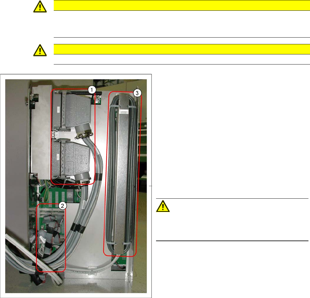
1. Harting connector
2. Flat ribbon cable
3. Ballast resistance
To remove the old axis unit, proceed as follows:
► Switch off the machine.
► Remove the protective cover above the axis unit, to
give you access to the axis unit.
► Pull the axis unit out of the machine.
► Lift the axis unit out of its guidance and place it down
on the ground.
► Unplug the Harting connector (1).
► Unplug all flat ribbon cables (2).
CAUTION!
Labeling the connectors
Label all flat ribbon cables to ensure correct reconnection
to the new axis unit, later on!
► Lift the ballast resistance (3) up and out and then un-
plug its connectors from the axis unit.