00194440-10_SM_X-Series_Customer_en.pdf - 第69页
Service Work 3.1.9 LED Assignment on the Subdistributor Electrics and Control Service Manual SIPLACE X Series 69 3.1.9 3 . 1 . 9 L E D A s s ig n m e n t o n t h e S u b d is t r ib u t o r LED Assignment on the Subdistr…

Service Work
Electrics and Control 3.1.8 Replacing the CAN Input/Output Module [00355051-xx]
68 Service Manual SIPLACE X Series
3.1.8
3.1.8 Replacing the CAN Input/Output Module [00355051-xx]
Replacing the CAN Input/Output Module [00355051-xx]
Overview
Removal/installation
► End all placement operations on the machine.
► Switch the machine off at the main switch.
► Remove the cover on the main distributor (5) in sector 2 or on the subdistributor (4) in sector 4.
► Mark the terminals on the CAN input/output module and remove these from the terminal strips and
connectors.
► Remove the assembly (3) from the fixation bar.
► Fit the new assembly and plug in all connections.
► Check the DIP switch (2) on the assembly. The switch position must be set according to the replaced
assembly.
► Check the firmware and perform a download, if needed.
See also
5.6.2 Checking the Firmware Function [ ➙ 350]
NOTICE
A further CAN input/output module is situated on the subdistributor (sector 4).
► The replacement follows the same procedure.
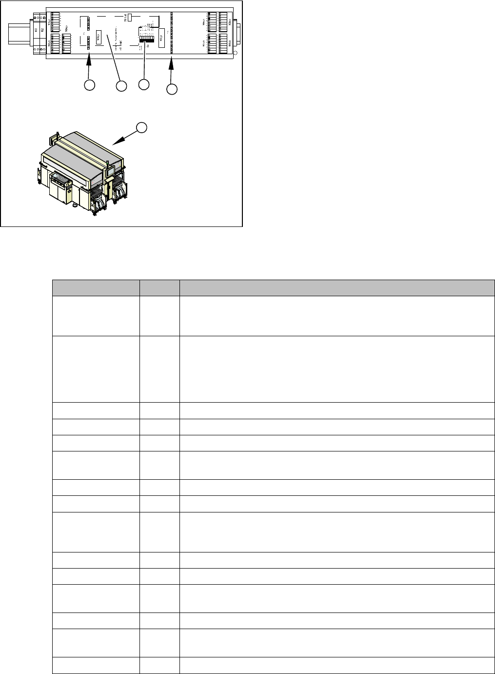
1. Installation point for 1 wire RS232 bridge (plugged in)
2. DIP switch
3. CAN input/output module assembly
4. Subdistributor
5. Main Distributor
Service Work
3.1.9 LED Assignment on the Subdistributor Electrics and Control
Service Manual SIPLACE X Series 69
3.1.9
3.1.9 LED Assignment on the Subdistributor
LED Assignment on the Subdistributor
3.1.9.1
3.1.9.1 I/O Module, Subdistributor (Inputs) [old: 03010005-05]
I/O Module, Subdistributor (Inputs) [old: 03010005-05]
nc = not connected (reserve)
1. LEDs Do 0 to Do 15 (digital outputs)
2. LEDs Di 0 to Di 23 (digital inputs)
3. Subdistributor
4. 1 wire RS232 bridge (plugged in)
5. DIP switch
► Remove the cover on the subdistributor (3) in
sector 4.
► The table below shows the LED assignment. If the
position is active, the LED will shine.
2
3
DI23
DI16
DI15
DI8
DI7
DI0
DO9
DO8
DO15
DO14
DO13
DO12
DO11
GND
GND
GND
P24
P24
P24
DO7
DO6
DO5
DO4
DO3
DO2
DO1
DO0
GND
P24
DO10
DI7
DI6
DI5
DI4
DI3
DI2
DI1
DI0
DI15
DI14
DI13
DI12
DI11
DI10
DI9
DI8
DI23
DI22
DI21
DI20
DI19
DI18
DI17
DI16
DI7_5V
DI6_5V
DI5_5V
DI4_5V
EG ND
EG ND
GND
VCC
DO15
DO0
DO0
DO8
4
5
1
Terminals I / O Description / Note
X3_1 Di0 M_NotAusSchleife1ok or M_Security Loop ("high" if all safety loops are
closed (protective hoods, emergency STOP buttons, component flaps,
changeover tables).
X3_2 Di1 M_D0ServoAdressBus Bit-0 of servo address!
Each servo assembly is assigned an ID number (0-16). This number can
be reconstructed from all 4 servo address bus messages. With the help
of the EA2/Do0 to EA2/Do4 outputs, each servo card can be addressed
in the intended slot.
X3_3 Di2 M_D1ServoAdressBus Bit-1 of servo address!
X3_4 Di3 M_D2ServoAdressBus Bit-2 of servo address!
X3_5 Di4 M_D3ServoAdressBus Bit of servo address!
X3_6 Di5 M_Drucksensor Hauptventil/ "high" signal when compressed air level is
reached
X3_7 Di6 M_Vakuumpumpe EIN
X3_8 Di7 nc
X4_1 Di8 M_StartTaste "high" signal while the start button is pressed. The function
of this button triggers the protective contactor combination, all axes are
ready for operation.
X4_2 Di9 M_StopTaste"high" signal while the stop button is pressed. .
X4_3 Di10 M_Abwurfbehälter
X4_4 Di11 M_ PortalCrash2 "low" signal gantries 1 and 4 too close,"high" signal is
normal operating status
X4_5 Di12 nc
X4_6 Di13 M_ ServoEnable2 or Steuerung Ein/"high" signal intermediate circuit volt-
age for X/Y servo on axis unit 2 - switched through. (K4 message)
X4_7 Di14 nc
Service Work
Electrics and Control 3.1.9 LED Assignment on the Subdistributor
70 Service Manual SIPLACE X Series
3.1.9.2
3.1.9.2 I/O Module, Subdistributor (Inputs) [new: 03046226-01]
I/O Module, Subdistributor (Inputs) [new: 03046226-01]
nc = not connected (reserve)
X4_8 Di15 M_ NotAusTasteMTC/"high" signal - emergency STOP button activated.
X5_1 Di16 nc
X5_2 Di17 M_ Haube1 "high" signal if cover 1 is closed.
X5_3 Di18 M_ BE-Tisch1 "high" signal if changeover table 1 is docked.
X5_4 Di19 M_ HaubeLP-Eingabe "high" signal if the cover above the PCB input is
closed.
X5_5 Di20 M_ NotAusTasteLP-Eingabe "high" signal if the emergency STOP button
is unlocked.
X5_6 Di21 M_ Haube4 "high" signal if cover 4 is closed.
X5_7 Di22 M_BE-Tisch4 "high" signal if changeover table 4 is docked.
X5_8 Di23 nc
X6_1 5 V
X6_2 GND
X6_3 GND
X6_4 GND
X6_5 nc
X6_6 nc
X6_7 nc
X6_8 nc
Terminals I / O Description / Note
Terminals I / O Description / Note
X3_1 Di0 M_NotAusSchleife1ok or M_Security Loop ("high" if all safety loops are
closed (protective hoods, emergency STOP buttons, component flaps,
changeover tables).
X3_2 Di1 nc
X3_3 Di2 nc
X3_4 Di3 nc
X3_5 Di4 nc
X3_6 Di5 M_Drucksensor Hauptventil/ "high" signal when compressed air level is
reached
X3_7 Di6 M_Vakuumpumpe EIN
X3_8 Di7 nc
X4_1 Di8 M_StartTaste "high" signal while the start button is pressed. The function
of this button triggers the protective contactor combination, all axes are
ready for operation.
X4_2 Di9 M_StopTaste"high" signal while the stop button is pressed. .
X4_3 Di10 nc
X4_4 Di11 M_ PortalCrash2 "low" signal gantries 1 and 4 too close,"high" signal is
normal operating status
X4_5 Di12 nc
X4_6 Di13 M_ ServoEnable2 or Steuerung Ein/"high" signal intermediate circuit volt-
age for X/Y servo on axis unit 2 - switched through. (K4 message)
X4_7 Di14 nc