00194440-10_SM_X-Series_Customer_en.pdf - 第71页
Service Work 3.1.9 LED Assignment on the Subdistributor Electrics and Control Service Manual SIPLACE X Series 71 3.1.9.3 3 . 1 . 9 . 3 I / O M o d u le f o r S u b d is t r ib u t o r ( O u t p u t s ) ( o ld ) I/O Modul…
Service Work
Electrics and Control 3.1.9 LED Assignment on the Subdistributor
70 Service Manual SIPLACE X Series
3.1.9.2
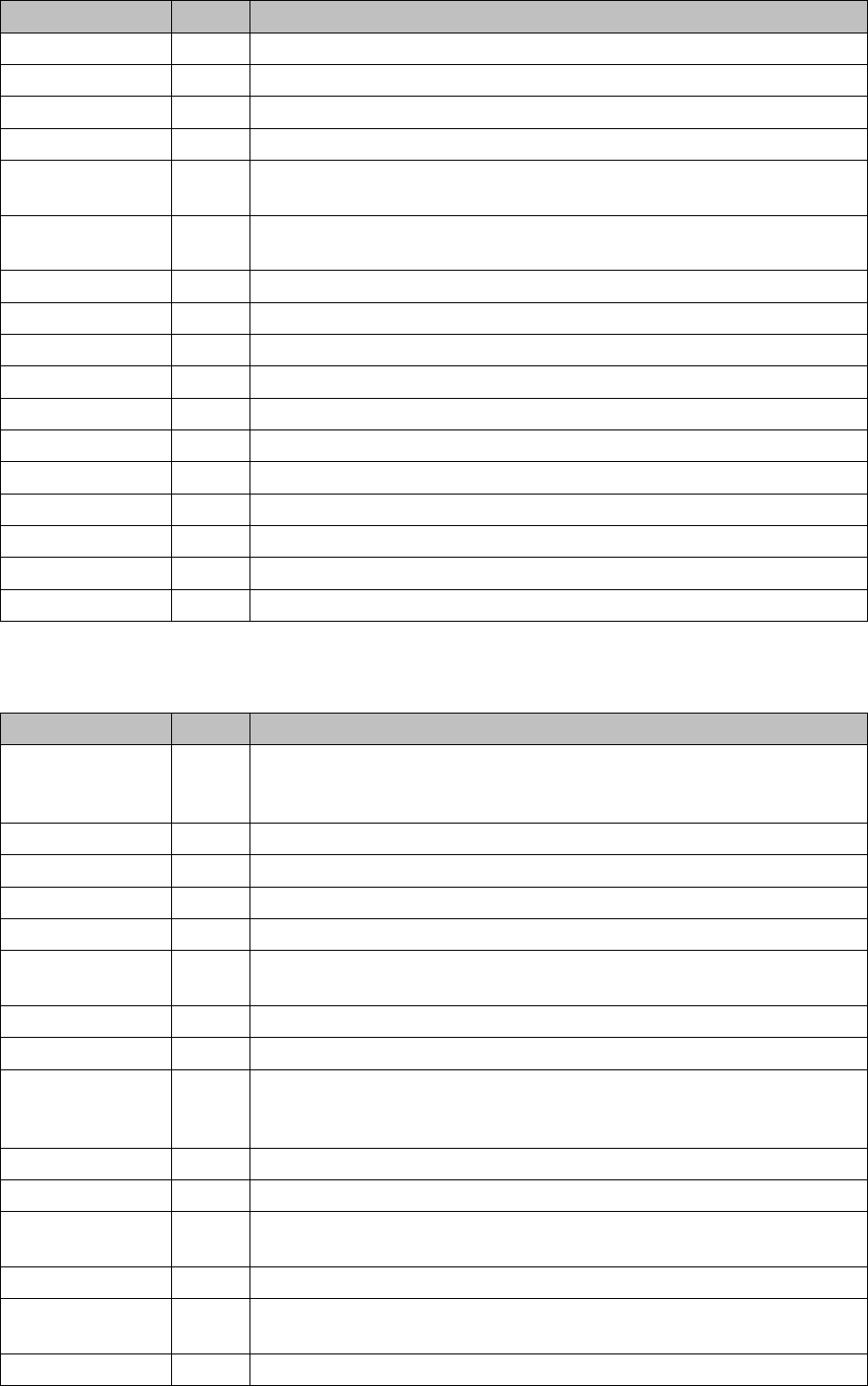
3.1.9.2 I/O Module, Subdistributor (Inputs) [new: 03046226-01]
I/O Module, Subdistributor (Inputs) [new: 03046226-01]
nc = not connected (reserve)
X4_8 Di15 M_ NotAusTasteMTC/"high" signal - emergency STOP button activated.
X5_1 Di16 nc
X5_2 Di17 M_ Haube1 "high" signal if cover 1 is closed.
X5_3 Di18 M_ BE-Tisch1 "high" signal if changeover table 1 is docked.
X5_4 Di19 M_ HaubeLP-Eingabe "high" signal if the cover above the PCB input is
closed.
X5_5 Di20 M_ NotAusTasteLP-Eingabe "high" signal if the emergency STOP button
is unlocked.
X5_6 Di21 M_ Haube4 "high" signal if cover 4 is closed.
X5_7 Di22 M_BE-Tisch4 "high" signal if changeover table 4 is docked.
X5_8 Di23 nc
X6_1 5 V
X6_2 GND
X6_3 GND
X6_4 GND
X6_5 nc
X6_6 nc
X6_7 nc
X6_8 nc
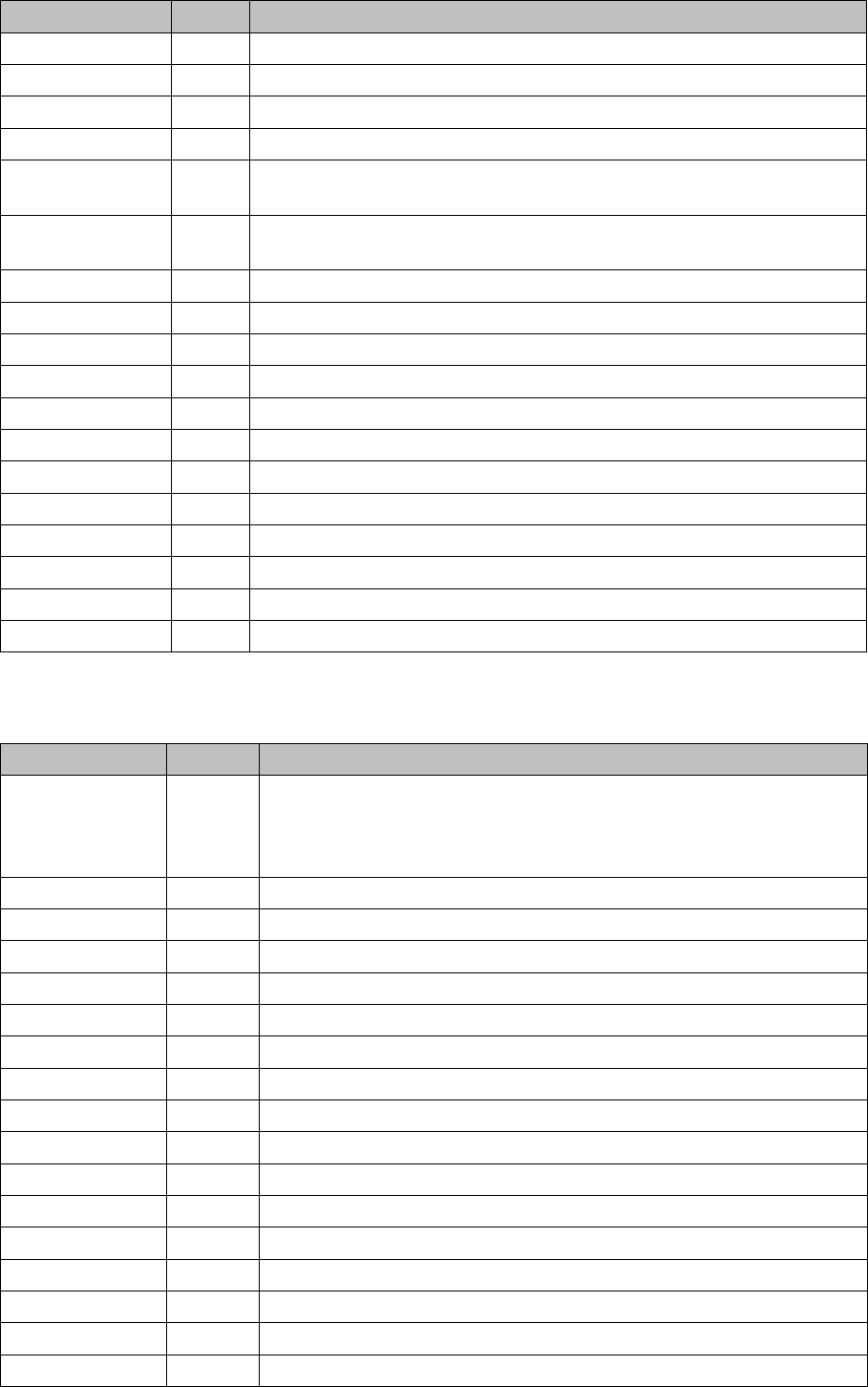
Terminals I / O Description / Note
Terminals I / O Description / Note
X3_1 Di0 M_NotAusSchleife1ok or M_Security Loop ("high" if all safety loops are
closed (protective hoods, emergency STOP buttons, component flaps,
changeover tables).
X3_2 Di1 nc
X3_3 Di2 nc
X3_4 Di3 nc
X3_5 Di4 nc
X3_6 Di5 M_Drucksensor Hauptventil/ "high" signal when compressed air level is
reached
X3_7 Di6 M_Vakuumpumpe EIN
X3_8 Di7 nc
X4_1 Di8 M_StartTaste "high" signal while the start button is pressed. The function
of this button triggers the protective contactor combination, all axes are
ready for operation.
X4_2 Di9 M_StopTaste"high" signal while the stop button is pressed. .
X4_3 Di10 nc
X4_4 Di11 M_ PortalCrash2 "low" signal gantries 1 and 4 too close,"high" signal is
normal operating status
X4_5 Di12 nc
X4_6 Di13 M_ ServoEnable2 or Steuerung Ein/"high" signal intermediate circuit volt-
age for X/Y servo on axis unit 2 - switched through. (K4 message)
X4_7 Di14 nc
Service Work
3.1.9 LED Assignment on the Subdistributor Electrics and Control
Service Manual SIPLACE X Series 71
3.1.9.3
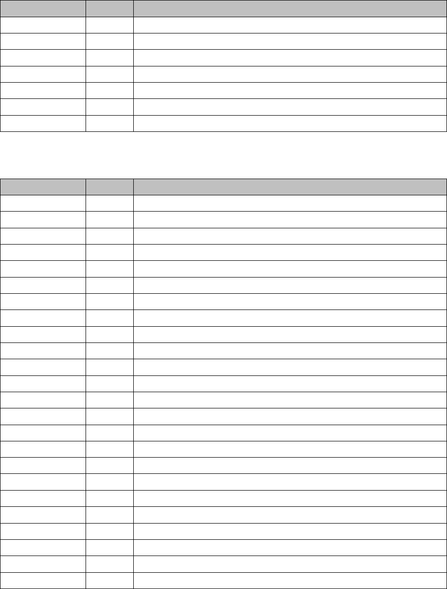
3.1.9.3 I/O Module for Subdistributor (Outputs) (old)
I/O Module for Subdistributor (Outputs) (old)
nc = not connected (reserve)
X4_8 Di15 M_ NotAusTasteMTC/"high" signal - emergency STOP button activated.
X5_1 Di16 nc
X5_2 Di17 M_ Haube1 "high" signal if cover 1 is closed.
X5_3 Di18 M_ BE-Tisch1 "high" signal if changeover table 1 is docked.
X5_4 Di19 M_ HaubeLP-Eingabe "high" signal if the cover above the PCB input is
closed.
X5_5 Di20 M_ NotAusTasteLP-Eingabe "high" signal if the emergency STOP button
is unlocked.
X5_6 Di21 M_ Haube4 "high" signal if cover 4 is closed.
X5_7 Di22 M_BE-Tisch4 "high" signal if changeover table 4 is docked.
X5_8 Di23 nc
X5_8 Di23 nc
X6_1 nc
X6_2 nc
X6_3 GND
X6_4 nc
X6_5 nc
X6_6 nc
X6_7 nc
X6_8 nc
Terminals I / O Description / Note
Terminals I / O Description / Note
X7_1 Do0 St_D0ServoSlot Bit-0 of servo slot ID! Each servo assembly is assigned
an ID number (0-16). This number can be reconstructed from all 4 servo
address bus messages. With the help of the EA2/Do0 to EA2/Do4 out-
puts, each slot intended for servo cards can be addressed.
X7_2 Do1 St_D1ServoSlot/Bit-1 of servo slot ID!
X7_3 Do2 St_D2ServoSlot/Bit-2 of servo slot ID!
X7_4 Do3 St_D3ServoSlot/Bit-3 of servo slot ID!
X7_5 Do4 St_D4ServoSlot/Bit-4 of servo slot ID!
X7_6 Do5 St_DruckluftHauptventil/A "low" signal opens the valve
X7_7 Do6 nc
X7_8 Do7 nc
X8_1 Do8 nc
X8_2 Do9 nc
X8_3 Do10 nc
X8_4 Do11 nc
X8_5 Do12
X8_6 Do13
X8_7 Do14
X8_8 Do15
X9_1 24 V
Service Work
Electrics and Control 3.1.9 LED Assignment on the Subdistributor
72 Service Manual SIPLACE X Series
3.1.9.4
3.1.9.4 I/O Module for Subdistributor (Outputs) (new)
I/O Module for Subdistributor (Outputs) (new)
nc = not connected (reserve)
X9_2 24 V
X9_3 24 V
X9_4 24 V
X9_5 GND
X9_6 GND
X9_7 GND
X9_8 GND
Terminals I / O Description / Note
Terminals I / O Description / Note
X7_1 Do0 nc
X7_2 Do1 nc
X7_3 Do2 nc
X7_4 Do3 nc
X7_5 Do4 nc
X7_6 Do5 St_Vakuumpumpe EIN
X7_7 Do6 nc
X7_8 Do7 nc
X8_1 Do8 nc
X8_2 Do9 nc
X8_3 Do10 nc
X8_4 Do11 nc
X8_5 Do12
X8_6 Do13
X8_7 Do14
X8_8 Do15
X9_1 24 V
X9_2 24 V
X9_3 24 V
X9_4 24 V
X9_5 GND
X9_6 GND
X9_7 GND
X9_8 GND