00194440-10_SM_X-Series_Customer_en.pdf - 第76页
Service Work Electrics and Control 3.1.10 LED Assignment on the Main Distributor 76 Service Manual SIPLACE X Series 3.1.10.4 3 . 1 . 1 0 . 4 I / O M o d u le f o r M a in D is t r ib u t o r ( O u t p u t s ) ( n e w ) I…
Service Work
3.1.10 LED Assignment on the Main Distributor Electrics and Control
Service Manual SIPLACE X Series 75
3.1.10.3
3.1.10.3 I/O Module for Main Distributor (Outputs) (old)
I/O Module for Main Distributor (Outputs) (old)
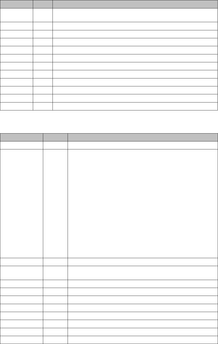
nc = not connected (reserve)
X5_5 Di20 M_NotAusTasteLP-Ausgabe "high" signal if the emergency STOP button is
unlocked.
X5_6 Di21 M_Haube3 "high" signal if cover 3 is closed.
X5_7 Di22 M_BE-Tisch3 "high" signal if changeover table 3 is docked
X5_8 Di23 nc
X6_1 nc
X6_2 nc
X6_3 GND
X6_4 nc
X6_5 nc
X6_6 nc
X6_7 nc
X6_8 nc
Terminals I / O Description / Note
Terminals I / O Description / Note
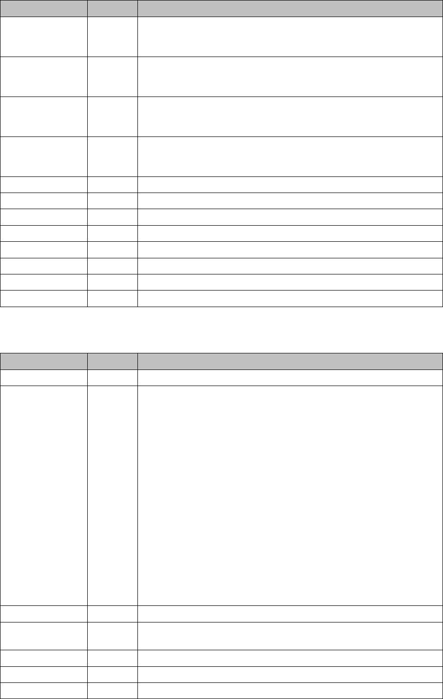
X7_1 Do0 nc
X7_2 Do1 St_Ein or software release
When a "high" signal is permanently supplied to this port (24 V), the HF
can be put into operation. The message M_Ready changes from "low"
to "high" (IO1/Di9), if relay K5 has latched (24 V). The emergency stop
loop1 and the start buttons to the protective contactor combination -
SSK (K6). Once all 6 hoods are closed, all 4 component flaps are
closed, the two EMERGENCY STOP buttons unlocked and all compo-
nent trolleys docked into place, the protective contactor combination
can be activated with one of the start buttons. The SSK (protective con-
tactor combination) switches:
1. The contactors K2, K3 and K4 on and the intermediate circuit volt-
age (somewhat delayed) is supplied to the X, Y and star servo axis
boards.
2. The operating voltage,
3. The compressed air (valve) to the tape cutters.
4. Two safety loops for the MTCs.
5. The operating voltage for the "PCB conveyor" motors on.
X7_3 Do2 St_Druckluft (VHS)
X7_4 Do3 St_DruckluftRV/TwinHead pneumatic OFF (a "low" signal opens the
compressed air main valve. A "high" signal closes this.
X7_5 Do4 St_BauteilZähler/Each "high" pulse increases the counter by one.
X7_6 Do5 nc
X7_7 Do6 nc
X7_8 Do7 nc
X8_1 Do8 nc
X8_2 Do9 nc
X8_3 Do10 nc
X8_4 Do11 nc
Service Work
Electrics and Control 3.1.10 LED Assignment on the Main Distributor
76 Service Manual SIPLACE X Series
3.1.10.4
3.1.10.4 I/O Module for Main Distributor (Outputs) (new)
I/O Module for Main Distributor (Outputs) (new)
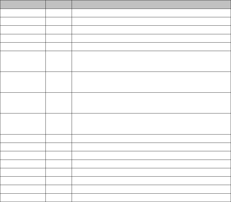
nc= not connected (Reserve)
X8_5 Do12 St_GrüneLampe1/The right-hand green light from the fault indicator
shines if a "high" signal is present at the port output. Meaning: Flashed
when no PCB board in the right conveyor lane.
X8_6 Do13 St_WeisseLampe1/The right-hand white light of the fault indicator lamp
shines if a "high" signal is present at the port output. Meaning: Fault on
a feeder on location 1 or 2.
X8_7 Do14 St_WeisseLampe2/The left-hand white light of the fault indicator
shines if a "high" signal is present at the port output. Meaning: Fault on
a feeder on location 3 or 4.
X8_8 Do15 St_GrüneLampe2/The left-hand green light from the fault indicator
shines if a "high" signal is present at the port output. Meaning: Flashed
when no PCB board in the left conveyor lane.
X9_1 24 V
X9_2 24 V
X9_3 24 V
X9_4 24 V
X9_5 GND
X9_6 GND
X9_7 GND
X9_8 GND
Terminals I / O Description / Note
Terminals I / O Description / Note
X7_1 Do0 nc
X7_2 Do1 St_Ein or software release
When a "high" signal is permanently supplied to this port (24 V), the HF
can be put into operation. The message M_Ready changes from "low"
to "high" (IO1/Di9), if relay K5 has latched (24 V). The emergency stop
loop1 and the start buttons to the protective contactor combination -
SSK (K6). Once all 6 hoods are closed, all 4 component flaps are
closed, the two EMERGENCY STOP buttons unlocked and all compo-
nent trolleys docked into place, the protective contactor combination
can be activated with one of the start buttons. The SSK (protective
contactor combination) switches:
1. . The contactors K2, K3 and K4 are switched on and the interme-
diate circuit voltage (somewhat delayed) is supplied to the X, Y and
star servo axis boards.
2. The operating voltage,
3. The compressed air (valve) to the tape cutters.
4. Two safety loops for the MTCs.
5. The operating voltage for the "PCB conveyor" motors on.
X7_3 Do2 nc
X7_4 Do3 St_DruckluftRV/Twin pneumatic OFF (a "low" signal opens the com-
pressed air main valve. A "high" signal closes this.
X7_5 Do4 St_BauteilZähler/Each "high" pulse increases the counter by one.
X7_6 Do5 nc
X7_7 Do6 nc
Service Work
3.1.10 LED Assignment on the Main Distributor Electrics and Control
Service Manual SIPLACE X Series 77
X7_8 Do7 nc
X8_1 Do8 nc
X8_2 Do9 nc
X8_3 Do10 nc
X8_4 Do11 nc
X8_5 Do12 St_GrüneLampe1/The right-hand green light from the fault indicator
shines if a "high" signal is present at the port output. Meaning: flashes
if no board is in the (right) conveyor lane.
X8_6 Do13 St_WeisseLampe1/The right-hand white light of the fault indicator lamp
shines if a "high" signal is present at the port output. Meaning: fault on
a feeder on location 1 or 2.
X8_7 Do14 St_WeisseLampe2/The left-hand white light of the fault indicator
shines if a "high" signal is present at the port output. Meaning: fault on
a feeder on location 3 or 4.
X8_8 Do15 St_GrüneLampe2/The left-hand green light from the fault indicator
shines if a "high" signal is present at the port output. Meaning: flashes
when no PCB in the (left) conveyor lane.
X9_1 24 V
X9_2 24 V
X9_3 24 V
X9_4 24 V
X9_5 GND
X9_6 GND
X9_7 GND
X9_8 GND
Terminals I / O Description / Note