00194440-10_SM_X-Series_Customer_en.pdf - 第77页
Service Work 3.1.10 LED Assignment on the Main Distributor Electrics and Control Service Manual SIPLACE X Series 77 X7_8 Do7 nc X8_1 Do8 nc X8_2 Do9 nc X8_3 Do10 nc X8_4 Do11 nc X8_5 Do12 St_Grü neLampe1/The ri ght- hand…

Service Work
Electrics and Control 3.1.10 LED Assignment on the Main Distributor
76 Service Manual SIPLACE X Series
3.1.10.4
3.1.10.4 I/O Module for Main Distributor (Outputs) (new)
I/O Module for Main Distributor (Outputs) (new)
nc= not connected (Reserve)
X8_5 Do12 St_GrüneLampe1/The right-hand green light from the fault indicator
shines if a "high" signal is present at the port output. Meaning: Flashed
when no PCB board in the right conveyor lane.
X8_6 Do13 St_WeisseLampe1/The right-hand white light of the fault indicator lamp
shines if a "high" signal is present at the port output. Meaning: Fault on
a feeder on location 1 or 2.
X8_7 Do14 St_WeisseLampe2/The left-hand white light of the fault indicator
shines if a "high" signal is present at the port output. Meaning: Fault on
a feeder on location 3 or 4.
X8_8 Do15 St_GrüneLampe2/The left-hand green light from the fault indicator
shines if a "high" signal is present at the port output. Meaning: Flashed
when no PCB board in the left conveyor lane.
X9_1 24 V
X9_2 24 V
X9_3 24 V
X9_4 24 V
X9_5 GND
X9_6 GND
X9_7 GND
X9_8 GND
Terminals I / O Description / Note
Terminals I / O Description / Note
X7_1 Do0 nc
X7_2 Do1 St_Ein or software release
When a "high" signal is permanently supplied to this port (24 V), the HF
can be put into operation. The message M_Ready changes from "low"
to "high" (IO1/Di9), if relay K5 has latched (24 V). The emergency stop
loop1 and the start buttons to the protective contactor combination -
SSK (K6). Once all 6 hoods are closed, all 4 component flaps are
closed, the two EMERGENCY STOP buttons unlocked and all compo-
nent trolleys docked into place, the protective contactor combination
can be activated with one of the start buttons. The SSK (protective
contactor combination) switches:
1. . The contactors K2, K3 and K4 are switched on and the interme-
diate circuit voltage (somewhat delayed) is supplied to the X, Y and
star servo axis boards.
2. The operating voltage,
3. The compressed air (valve) to the tape cutters.
4. Two safety loops for the MTCs.
5. The operating voltage for the "PCB conveyor" motors on.
X7_3 Do2 nc
X7_4 Do3 St_DruckluftRV/Twin pneumatic OFF (a "low" signal opens the com-
pressed air main valve. A "high" signal closes this.
X7_5 Do4 St_BauteilZähler/Each "high" pulse increases the counter by one.
X7_6 Do5 nc
X7_7 Do6 nc

Service Work
3.1.10 LED Assignment on the Main Distributor Electrics and Control
Service Manual SIPLACE X Series 77
X7_8 Do7 nc
X8_1 Do8 nc
X8_2 Do9 nc
X8_3 Do10 nc
X8_4 Do11 nc
X8_5 Do12 St_GrüneLampe1/The right-hand green light from the fault indicator
shines if a "high" signal is present at the port output. Meaning: flashes
if no board is in the (right) conveyor lane.
X8_6 Do13 St_WeisseLampe1/The right-hand white light of the fault indicator lamp
shines if a "high" signal is present at the port output. Meaning: fault on
a feeder on location 1 or 2.
X8_7 Do14 St_WeisseLampe2/The left-hand white light of the fault indicator
shines if a "high" signal is present at the port output. Meaning: fault on
a feeder on location 3 or 4.
X8_8 Do15 St_GrüneLampe2/The left-hand green light from the fault indicator
shines if a "high" signal is present at the port output. Meaning: flashes
when no PCB in the (left) conveyor lane.
X9_1 24 V
X9_2 24 V
X9_3 24 V
X9_4 24 V
X9_5 GND
X9_6 GND
X9_7 GND
X9_8 GND
Terminals I / O Description / Note
Service Work
Electrics and Control 3.1.11 Replacing the Protective Cover Switch [03020409-XX]
78 Service Manual SIPLACE X Series
3.1.11
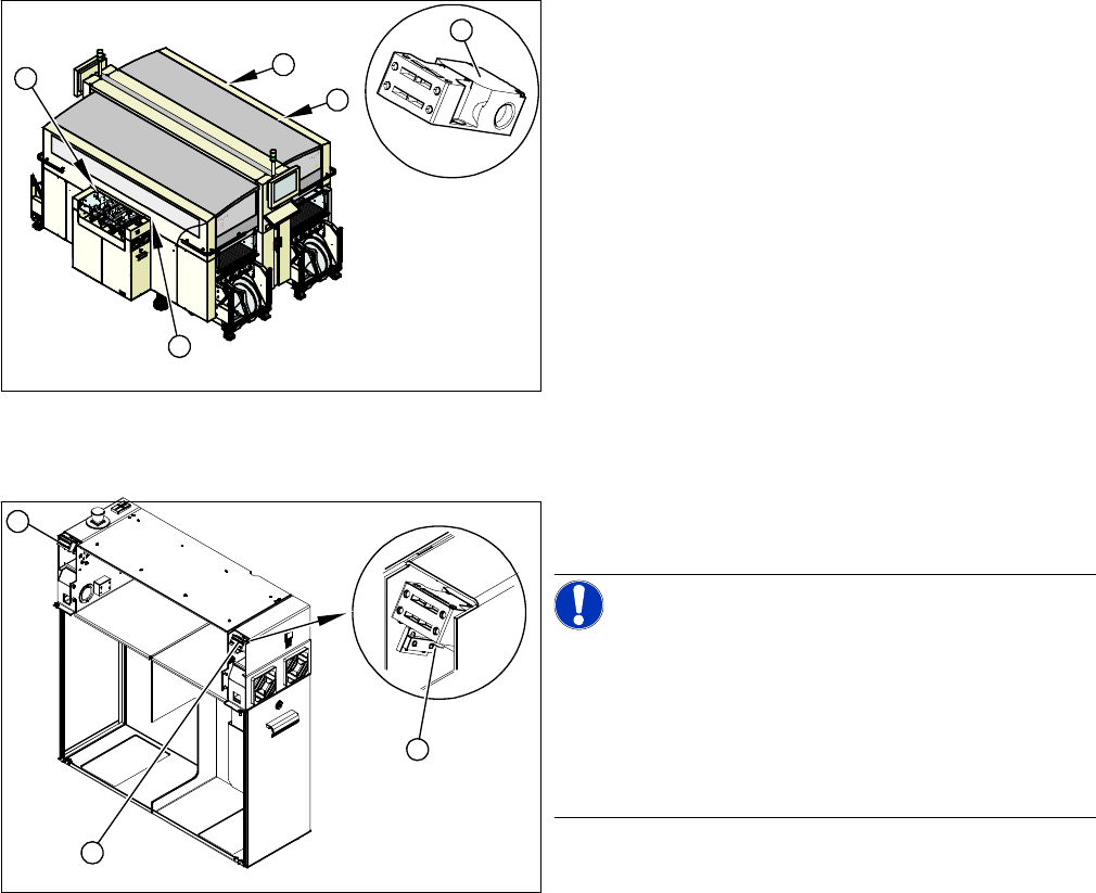
3.1.11 Replacing the Protective Cover Switch [03020409-XX]
Replacing the Protective Cover Switch [03020409-XX]
Overview
Removal/Installation
► Label the appropriate connections at the main or intermediate distributor.
► Unplug the connection cable.
► Unthread the connection cable as far as the cover switch. Where necessary, dismantle the covers.
► Loosen the screws fastening the cover switch.
► Fit the new cover switch.
► Rethread the connection cable and plug in the electrical connections.
► Close the protective cover and check that the cover switch engages properly and is actuated.
► Correct the position of the cover switch at the slots.
► Switch the machine on and check that the cover switch activates the safety circuit, when the protec-
tive cover is opened.
► Refit the covers.
1. Installation position of cover switch at the input/output
side (when cover is open)
2. Cover switch with connection cable, complete
1
1
1
1
2
1. Cover switch
2. Fastening screws
NOTICE!
Connection cable for cover switch
The connection cables for the cover switch are either run
to the main or intermediate distributor, depending on the
location. Refer to the circuit diagram folders for the re-
spective machine.
Where necessary, dismantle the covers.
1
1
2