00194440-10_SM_X-Series_Customer_en.pdf - 第90页
Service Work Gantries 3.3.4 Replacing the End Positio n / Refe rence Proximity S w it c h f o r t h e Y A xi s 90 Service Manual SIPLACE X Series 3.3.4 3 . 3 . 4 R e p la c in g t h e E n d P o s it io n / R e f e r e n …
Service Work
3.3.3 Replacing the Y Axis Incremental Encoder [03090202-xx] Gantries
Service Manual SIPLACE X Series 89
See also
5.1.7 Track Signals and Zero Pulse [ ➙ 266]
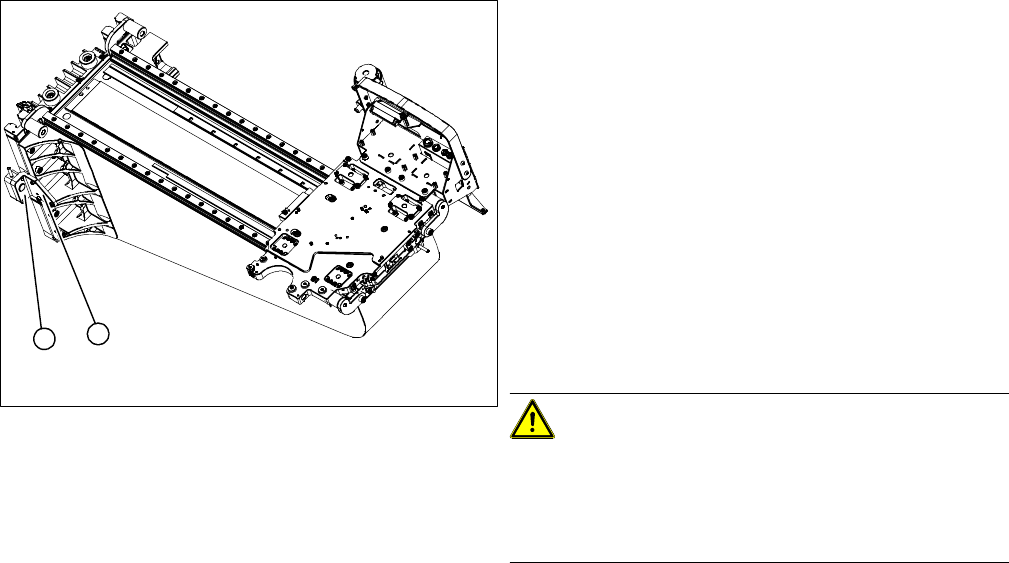
► Unthread the connection cable as far as the incre-
mental encoder.
► Loosen the three screws fastening (1) the incremen-
tal encoder (2) of the Y axis and carefully lift off the
incremental encoder (2).
► Clean the reading surface of the incremental encoder
with a cloth and ethanol or with a Q tip.
► Install the incremental encoder (2) with the three fas-
tening screws so that there is a gap of 0.75 mm be-
tween the incremental encoder (2) and the scale (for
old read head [03003751-xx] 0.4 mm). Use the corre-
sponding thickness gauge (plastic).
► Reconnect to the electricity supply (connector X9 or
X10 on gantry interface).
CAUTION!
Make sure that the cables do not rub against anything.
Make sure that the axes can be moved without damaging
the cables.
Fasten them with cable ties.
1
2
Service Work
Gantries 3.3.4 Replacing the End Position / Reference Proximity Switch for the Y Axis
90 Service Manual SIPLACE X Series
3.3.4
3.3.4 Replacing the End Position / Reference Proximity Switch for the Y Axis [03004106-xx]
Replacing the End Position / Reference Proximity Switch for the Y Axis [03004106-xx]
Parts
▪ Y axis end position proximity switch [03004106-xx]
▪ Reference point proximity switch for the Y axis [03004107-xx]
Removal/Installation
NOTICE
Only for machines with axis card A363
These proximity switches are not needed for machines using the A364 axis card (from X-Series
MA No. B-337 and X4I).
The end position/reference proximity switch function is included in the A364 axis card.
CAUTION
Use the heat-shrinkable sleeve for the cable duct
The proximity switch cables are fastened to the gantry with a heat-shrinkable sleeve so that
they will not rub or come loose during travel. Try to pull the proximity switch cable through this
sleeve so that you can reuse it. If this is not possible, you will need to slide over a new heat-
shrinkable sleeve.
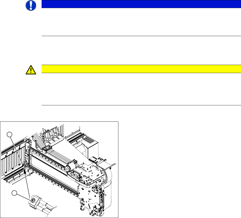
1. Position of end position proximity switch Y axis and
reference point proximity switch Y axis.
This sensor has no longer been fitted since the intro-
duction of the axis card 364 (from ma. no. 357).
2. End position proximity switch mount
► Unplug the press-fit connections for the end position
proximity switch (1) or reference proximity switch (1)
from the gantry interface.
► Unthread the connection cable as far as the proximity
switches.
► Loosen the screw fastening the proximity switch
mount (2).
1
2
Service Work
3.3.4 Replacing the End Position / Reference Proximity Switch for the Y Axis [03004106-xx] Gantries
Service Manual SIPLACE X Series 91
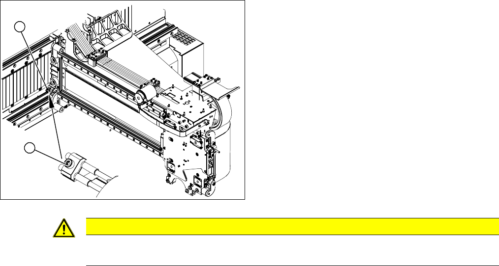
► Replace the relevant proximity switch and install the
proximity switch mount with the proximity switches.
► Make sure there is a gap of 0.4 mm between the prox-
imity switches and the trigger bar. Use the corre-
sponding thickness gauge (plastic).
► Reconnect to the electricity supply.
► Make sure that the cables do not rub against any-
thing. Pull the cable through the heat-shrinkable
sleeve or attach a new sleeve.
1
2
CAUTION
Check how the cables are run!
Make sure that the axes can be moved without damaging the cables.