00194440-10_SM_X-Series_Customer_en.pdf - 第96页
Service Work Gantries 3.3.7 Replacing the PCB Camera [00355462-xx] 96 Service Manual SIPLACE X Series Installation 3.3.7 3 . 3 . 7 R e p la c in g t h e P C B C a m e r a [ 0 0 3 5 5 4 6 2 - x x ] Replacing the PCB Camer…
Service Work
3.3.6 Replacing the Head Plate Sensor [03013143-xx] Gantries
Service Manual SIPLACE X Series 95
3.3.6
3.3.6 Replacing the Head Plate Sensor [03013143-xx]
Replacing the Head Plate Sensor [03013143-xx]
Removal
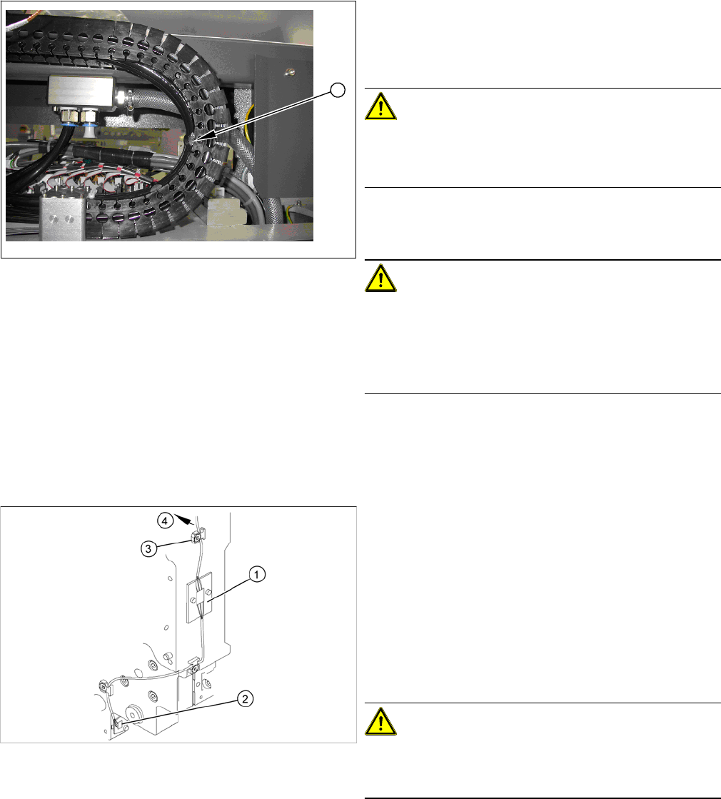
► Check how the tubes are run in the U profile.
The tube must not be stretched at fixture position 10 (1)
in any end position. Please refer to the photo on the left
for the maximum permissible tension.
CAUTION!
Observe the length and bending radius of the tube!
If the tube is shorter and the bending radius therefore
smaller, discard it and run a new tube.
► Run the tubes to the Y axis motor and connect it.
► Fix the tubes to the flange with cable ties.
CAUTION!
Ensure that the cooling tubes are firmly attached to the Y
motor and distributor and that they have been fixed with
cable ties.
If the cooling tubes loosen, the Y motor will not be cooled
properly.
1
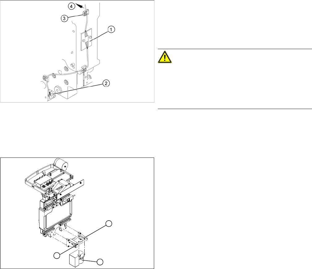
1. Temperature sensor 1 (board)
2. Temperature sensor 2 (board)
3. Cable clamps
4. To the head interface
► Unplug the cable (4) at the head interface, unthread
it and release all cable clamps (3).
► Undo and remove the two screws fastening the first
board (1).
CAUTION!
There is another small board under this board. This does
not need to be replaced and must remain in the head
plate.
► Loosen the screw fastening the second board (2).
Service Work
Gantries 3.3.7 Replacing the PCB Camera [00355462-xx]
96 Service Manual SIPLACE X Series
Installation
3.3.7
3.3.7 Replacing the PCB Camera [00355462-xx]
Replacing the PCB Camera [00355462-xx]
Removal/installation
► Fasten the board (1) with the two screws provided.
Take care of the contacts to the board fitted below.
► Fasten the second board (2) into place.
► Insert the cable (4), thread through to the head inter-
face and then connect.
CAUTION!
Check how the cables are run!
Make sure that the end stops (red buffers) do not rub
against the cable of the first board.
Make sure that the cable for the second board can not
collide with the X axis end stopper.
► Unplug the connection cable at the head board and
unthread it as far as the PCB camera (1).
► Loosen the two screws on the damping bracket (2).
► Loosen the three screws fastening the PCB camera
mount (3).
► Install the new PCB camera on the mount (3). Tight-
en the screws and secure with loctite 241.
► Tighten the two screws fastening the damping brack-
et (2).
► Run the connection cable to the head board and re-
connect to the electrical system.
1
3
2

Service Work
3.3.8 Replacing the Trailing Cable Gantries
Service Manual SIPLACE X Series 97
3.3.8
3.3.8 Replacing the Trailing Cable
Replacing the Trailing Cable
3.3.8.1
3.3.8.1 Introduction
Introduction
This manual describes the installation and removal of the trailing cable for Siplace HF and X-Series ma-
chines in their various versions.
This manual sometimes uses diagrams of the SIPLACE HF machine. However, this does not affect the
installation and removal for X series machines. If there are differences between the two machines types,
which need to be observed, this will be indicated on the diagrams.
3.3.8.2
3.3.8.2 Overview of SIPLACE HF Variants
Overview of SIPLACE HF Variants
Trailing cable HF
Depending on the arrangement of gantries, there are three different trailing cable types available for
SIPLACE HF machines.
▪ Trailing cable for HF machines at gantry 1 in a placement area with one gantry
HF gantry 1 or 3, HF3 gantry 3
– [03039706S01] Trailing cable analog 1P
▪ Trailing cable for HF machines in a placement area with two gantries and an uneven number
HF3 gantry 1
– [03039708S01] Trailing cable analog 2P U
▪ Trailing cable for HF machines in a placement area with two gantries and an even number:
HF3 Portal 4
– [03039709S01] Trailing cable analog 2P G
NOTICE
Downwards compatibility
These versions of the trailing cable can also be used with SIPLACE HF machines up to ma-
chine number A-219, in conjunction with the "Trailing cable retrofit kit" [03046248-01]. This ret-
rofit kit is included in the trailing cable spare parts set.
► Fit the new cable supports.