YS100_Mainte_E.pdf - 第110页
3-45 3 Periodic maintenance items 5. Six-month inspection 5.1 Cleaning the fiducial camera T he fiducial mark recognition camera is mounted on the right of the head unit. T he camera unit may become dirty with dust due t…
3-44
3
Periodic maintenance items
4
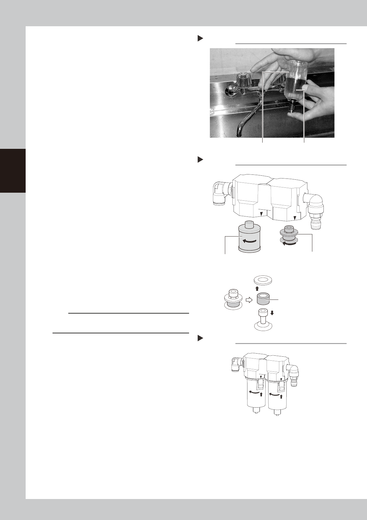
Clean the inside of the filter cup.
1. Lightly clean the filter cup with water.
2. Pour water-diluted neutral detergent into
the filter cup and clean the inside.
3. After blowing air to the filter cup, wipe
away any moisture with cloth.
53359-L1-00
5
Remove the filter element.
Air filter:
Turn the element ASSY counterclockwise
to remove.
The filter element is set between the top
and bottom adapters.
Oil mist filter:
Turn the filter element counterclockwise
to remove.
53369-L1-00
6
Check the state of element.
Check there is no dirt and clogging in the
filter element. If dirt and clogging are found,
replace with a new filter element.
7
Attach the filter element.
Follow the reverse order of removing the
element to remove the filter element.
8
Attach the cup.
1. Match the button of the cup with the
mark on the filter housing, and push the
cup upward.
2. Turn the cup 45 degrees to left.
53370-L1-00
TIP
When the cup is in place correctly, you hear a clicking
sound.
9
Reconnect the air coupler.
1. After reconnecting the air coupler, check
that no air is leaking.
2. Turn the “Air supply/exhaust” switch
counterclockwise to restart air supply.
Cleaning the filter cup
Step 4
Filter cup
Water-diluted
neutral detergent
Removing the filter element
Step 5
Mist filter element
(Air) filter element
Filter element ASSY
Reattaching the cup
Step 8
3-45
3
Periodic maintenance items
5. Six-month inspection
5.1 Cleaning the fiducial camera
The fiducial mark recognition camera is mounted on the right of the head unit.
The camera unit may become dirty with dust due to the long-term use of the machine. Periodic cleaning is
recommended.
c
CAUTION
Do not apply strong force or shock to the camera unit and lighting unit during cleaning. Optical axis adjustment might
become unreliable.
c
CAUTION
If trouble occurs with the lighting unit, then contact YAMAHA sales representative. Disassembly and cleaning of the
lighting unit by the user will void the warranty.
e
1
Move the head unit.
1. Press the emergency stop button to open
the machine safety cover.
2. Move the head unit forward.
2
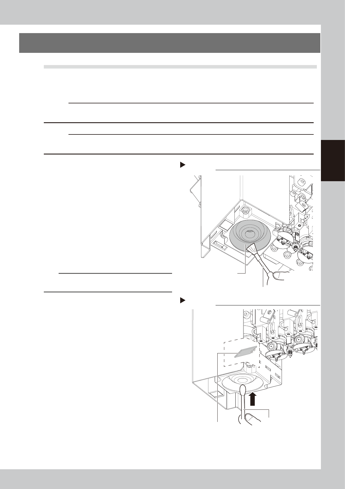
Clean around the lens.
Remove dust around the lens with the
blower brush.
53386-L1-00
3
Clean the lens.
Apply a small amount of lens cleaner on a
cotton swab, and clean the lens.
53387-L1-00
TIP
The blower brush and lens cleaner are optional
purchase items.
Step 2
Using a blower brush to remove dust
Fiducial camera lighting unit
Blower brush
Step 3
Cotton swab dampened
with lens cleaner
Cleaning the reflector plate
Reflector plate
3-46
3
Periodic maintenance items
5.2 Cleaning and lubricating the W-axis
The following describes the cleaning and lubrication procedures for the W-axis. For details about lubrication
points and styles, see "Chapter 5 Lubrication points and schedule".
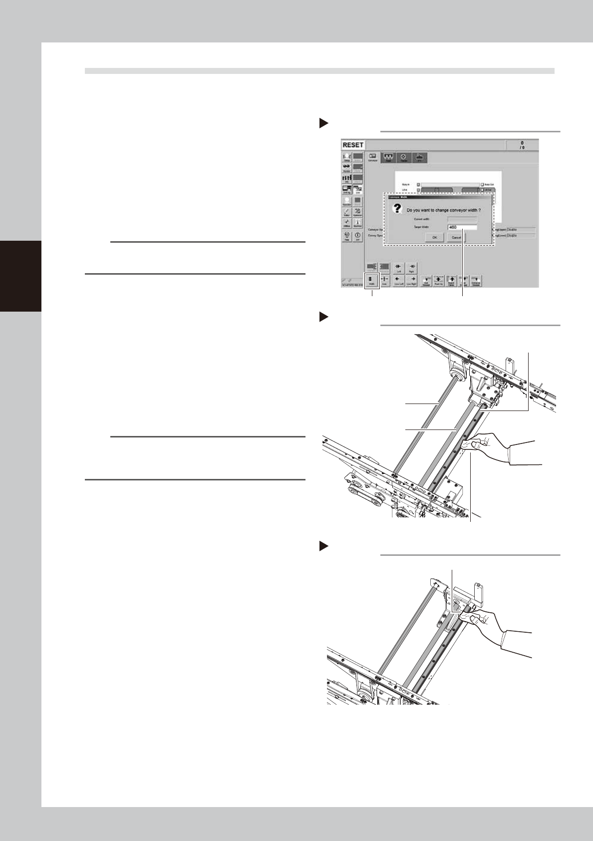
1
Change the conveyor width to its
maximum width.
1. Press the [Width] button to display the
"Conveyor Width" screen.
2. Enter the maximum value of the
conveyor width in the "Target Width" box
and press the [OK] button. The conveyor
width is changed to the specified width.
54315-L1-00
TIP
The maximum conveyor width is 460 mm or 410 mm as
a standard feature.
e
2
Clean the each part of W-axis.
1. Press the emergency stop button and
then open the machine safety cover.
2. If the machine is equipped with a
carriage, remove the carriage to easily
access to the W-axis.
3. Wipe the old grease and soiling from the
2 ball screws, a hexagon spline and 2
guides with a lint-free cloth.
53388-L1-00
n
NOTE
Carefully wipe the lead grooves of the ball screw during
the cleaning work. Additionally, make sure that any dirt
is not produced.
3
Change the conveyor width to its
minimum width.
1. Close the machine safety cover and
cancel the emergency stop.
2. Press the [Width] button to display the
"Conveyor Width" screen.
3. Enter the minimum value of the conveyor
width "50 mm" in the "Target Width" box
and press the [OK] button. The conveyor
width is changed to the specified width.
e
4
Clean the rest of the part.
1. Press the emergency stop button and
then open the machine safety cover.
2. Wipe off the remaining grease or soiling
describes in Step 2 with a lint-free cloth.
53389-L1-00
Step 2
Cleaning the W-axis
Ball screw
Cleaning cloth
Hexagon spline
Guide
Step 4
Cleaning the W-axis 2
Wipe off remaining grease or soiling.
Step 1
[Width] button Enter the maximum conveyor width.
Changing the conveyor width