YS100_Mainte_E.pdf - 第113页
3-48 3 Periodic maintenance items 5.3 Cleaning the side view camera (Option) T he side view camera (Option) consists of the lighting unit on the head unit side and the identification camera on the X axis frame side. The …
3-47
3
Periodic maintenance items
5
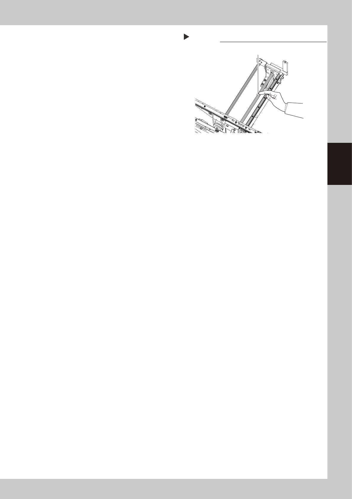
Apply grease.
Apply the specified grease (NSL) with finger
uniformly over the surfaces of the hexagon
spline and the ball screw and lead grooves
while the conveyor is the minimum width.
53390-L1-00
6
Change the conveyor width to its
maximum width.
1. Close the machine’s safety cover, and
cancel the emergency stop. If the
machine could be equipped with a
carriage, set the carriage.
2. Follow Step 1 and make the conveyor
width to the maximum.
e
7
Apply the remaining grease.
1. Press the emergency stop button and
open the machine’s safety cover. If the
machine is equipped with a carriage,
remove the carriage.
2. Apply grease to the places where grease
could not be applied in Step 5.
8
Spread the grease.
1. Close the machine’s safety cover, and
cancel the emergency stop. If the
machine could be equipped with a
carriage, set the carriage.
2. Change the conveyor width from
maximum to minimum several times with
the procedures of Step 1 and 3.
e
9
Wipe away excess grease.
1. Press the emergency stop button and
open the machine’s safety cover. If the
machine is equipped with a carriage,
remove the carriage.
2. Wipe all excess grease from end faces of
hexagon spline, the ball screw and the
guide.
Step 5
Applying grease
Grease
(Apply grease in a uniform manner.)
3-48
3
Periodic maintenance items
5.3 Cleaning the side view camera (Option)
The side view camera (Option) consists of the lighting unit on the head unit side and the identification camera
on the X axis frame side. The camera lens and diffuser plate may get dirty with dust; therefore, it is
recommended to clean them periodically.
c
CAUTION
Do not apply strong force or shock to the camera unit and lighting unit during cleaning. Optical axis adjustment might
become unreliable.
c
CAUTION
If trouble occurs with the lighting unit, then contact YAMAHA sales representative. Disassembly and cleaning of the
lighting unit by the user will void the warranty.
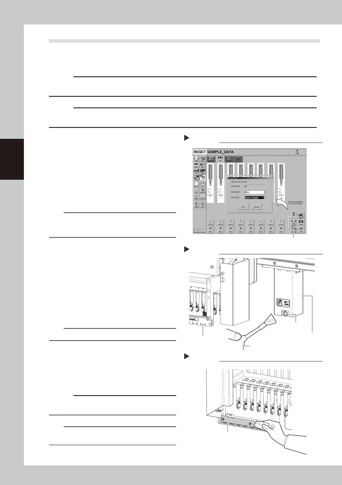
1
Store all nozzles.
1. Press the [Nozzle Change] button on the
[Unit] – [Head] screen.
2. In the “Nozzle Change” screen, select
“ALL” for the head number, and “Store
Nozzles” for the nozzle type.
3. Press the [OK] button, and all nozzles
except for the FNC head are stored in
the nozzle station.
n
NOTE
When a nozzle station is not equipped, press the
emergency stop button, and remove the nozzle with
hand.
54317-L1-00
e
2
Move the head unit forward.
1. Press the emergency stop button and
then open the machine safety cover.
2. Move the head unit forward.
3
Clean the lens.
Remove the dust around the lens of the side
view camera using the blow brush.
53391-L1-00
TIP
The blower brush must be purchased as an option.
4
Clean the diffuser plate.
Check the diffuser plate visually, and if dust
or stain is visible, wipe lightly with a dry
cleaning cloth.
53392-L1-00
c
CAUTION
Do Not use a solvent. It may cause decolorization of the
diffuser plate.
n
NOTE
When the nozzle is removed with hand, always put it
back to the position where it was removed.
Storing nozzles
Step 1
[Nozzle Change] button
Clean the lens
Step 3
Lens
Identification camera
Lighting unit
Blower brush
Clean the diffuser plate
Step 4
Diffuser plate
3-49
3
Periodic maintenance items
6. One-year inspection
6.1 Cleaning and replacing the blow station filter
To clean or replace the blow station filter, follow the steps below.
c
CAUTION
If trouble occurs with the blow station, contact YAMAHA
sales representative. Disassembly and cleaning of the
blow station by the user will void the warranty.
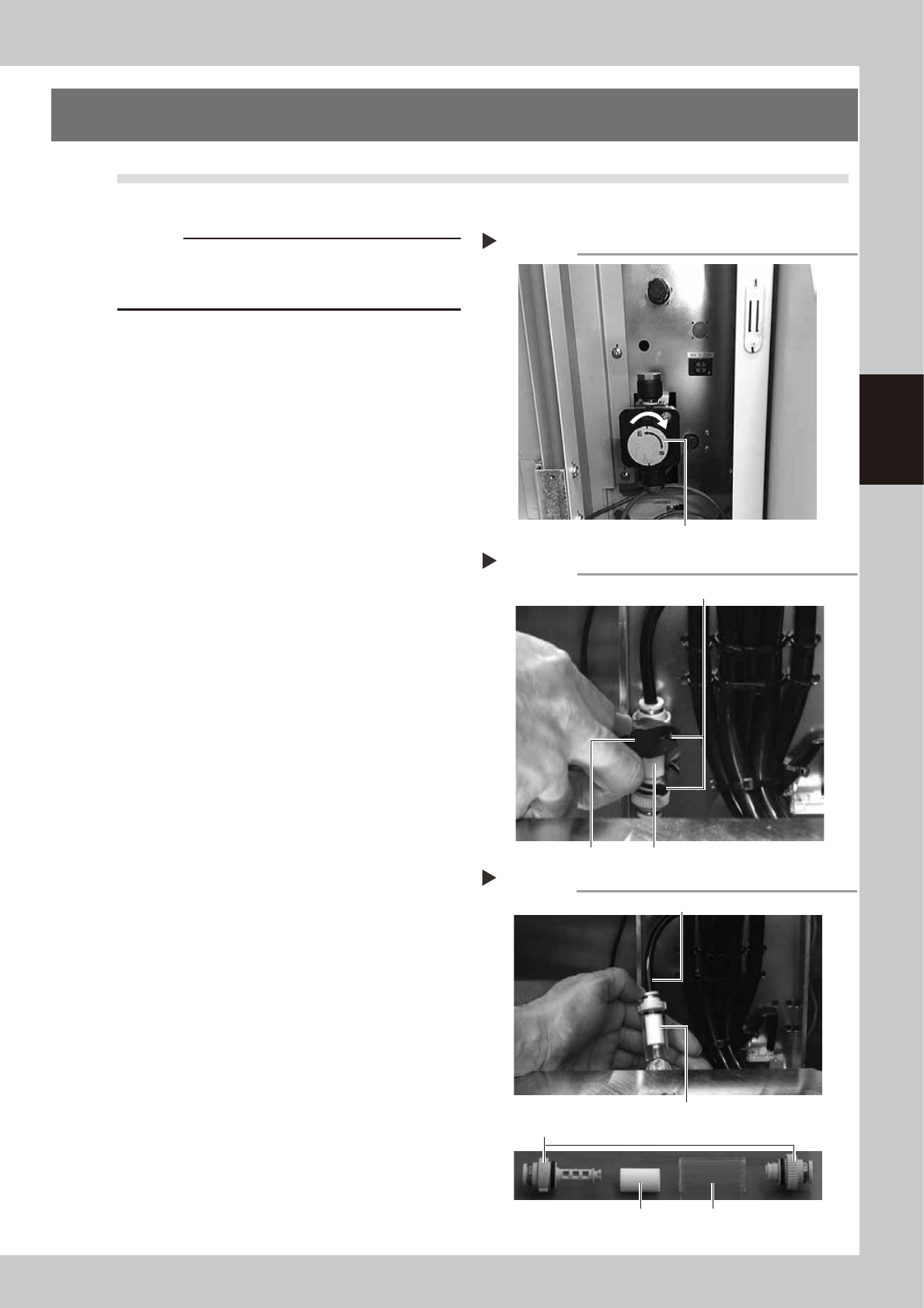
1
Turn the machine’s sir supply OFF.
Turn the "air supply/exhaust" switch inside
the panel at lower left of the machine
clockwise to turn the air supply OFF.
53364-L1-10
e
2
Cut the cable ties on the filter.
1. Press the emergency stop button and
open the machine’s safety cover. If the
machine is equipped with a carriage,
remove the carriage.
2. Using a wire cutter or similar tool, cut the
cable ties that hold the filter unit inside
the blow station stand.
53365-L1-00
3
Disconnect the air hose from one
end of the filter unit and remove
the filter.
1. Disconnect the air hose from one end of
the in-line filter unit.
2. Remove the filter joint caps on both sides
of the filter by rotating them 90 degrees.
3. Pull the transparent case to remove it
and remove the filter.
53366-L1-00
4
Clean the filter.
Use an air blow tool (option) to blow air
through the filter from the inside and from
the outside. If the filter is excessively dirty
and cannot be cleaned, replace it with a
new filter.
5
Return the filter
Place the filter with new cable ties.
Cutting the cable tie
Step 2
Cable tie
Wire cutter In-line filter unit
Taking out the filter
Step 3
Air hose
Filter
Transparent filter case
In-line filter unit
Filter joint caps
Shutting off the air supply
Step 1
Air supply/shutoff valve