YS100_Mainte_E.pdf - 第138页
A-2 Appendix 1.2 Power connection terminals T he power connection terminals are located inside the lower right panel on the front of the machine. Connect the power cable leads as shown belo w to the L1, L2, L3 and ground…
A-1
Appendix
1. Specifications
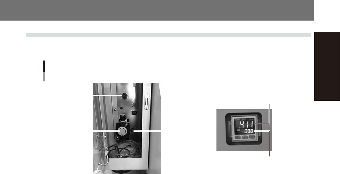
1.1 Air regulator unit
The air regulator for controlling the air pressure to the pneumatic units of the machine is located behind the
front lower left panel. A digital pressure gauge is provided on the front left of the machine.
Air pressure regulator and pressure gauge
Air supply/shutoff
valve
Air release valve
(for tape cutter)
Air pressure
regulator
Air pressure setting for machine
Pressure-drop detection level
53A00-L1-00
n
Supply air pressure
This is the pressure of the source air supplied to the machine. Before setting the air pressure with the air regulator, make
sure that this supply air pressure is in the following optimal range.
0.45MPa to 0.7MPa
n
Digital pressure gauge
Shows the supply air pressure (upper reading) and pressure-drop detection level (lower reading). A normal pressure value
is shown in green, and a pressure value lower than the pressure-drop detection level is shown in red.
n
Air pressure setting and pressure-drop detection level
Air pressure setting for machine (upper reading) : 0.40MPa to 0.41MPa
Pressure-drop detection level (lower reading) : 0.33MPa
n
Air supply/shutoff switch
Turning this valve to the right shuts off air supply and also discharges the air remaining in the air path.
n
Air release valve (for tape cutter)
Turning this valve to the right shuts off air supply to the tape cutter and also discharges the air remaining in the air path.
n
Source air connector
Prepare an air hose with an inner diameter of at least 8mm having a 40SH socket (Nitto Koki, or equivalent), and connect
it to this connector. Use dry, clean air passed through an air filter.
A-2
Appendix
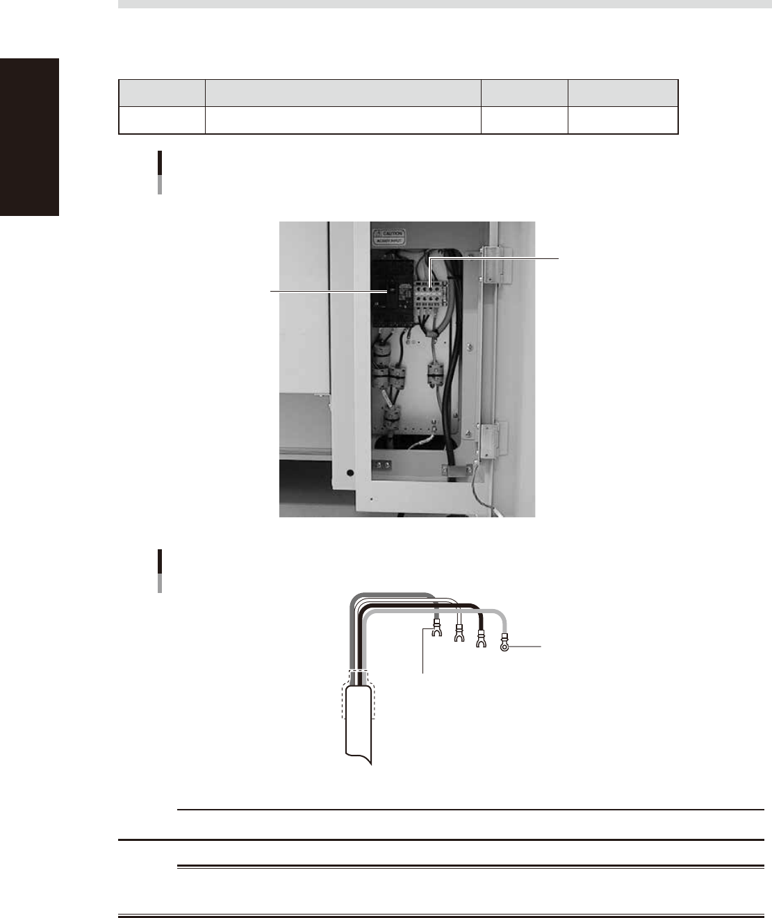
1.2 Power connection terminals
The power connection terminals are located inside the lower right panel on the front of the machine. Connect
the power cable leads as shown below to the L1, L2, L3 and ground terminal (PE) on the power terminal block.
n
Power supply specifications
Model name Power Frequency Power capacity
YS100 3-phase AC 200/208/220/240/380/400/416V (±10%) 50/60Hz 5.2kVA
Power input terminals
(L1, L2, L3) and ground terminal
Main breaker
Power connection terminals
53A01-L1-00
Fork-tongue crimp terminal
Power cable example
L1
L2
L3
PE
L=100mm
Ring-tongue crimp terminal
53A02-L1-00
c
CAUTION
Use a power cable whose conductor cross-section area is greater than 2.5mm
2
.
w
WARNING
TO AVOID THE RISK OF ELECTRICAL SHOCK, MAKE SURE THAT THE POWER SOURCE IS OFF BEFORE CONNECTING THE
POWER CABLE. ALSO MAKE SURE THAT THE GROUND CABLE IS SECURELY CONNECTED TO THE MACHINE.

A-3
Appendix
2. Warranty
The machine you have purchased is warranted against malfunctions as described below.
n
Warranty description:
If a failure or breakdown occurs due to defects in workmanship or materials used to manufacture this machine within
one year or 5,000 hours of operation (whichever comes first) after the incoming inspection is complete, then YAMAHA
will repair the defective parts free of charge.
n
Warranty period
The warranty period ends when any of the following applies:
1. After one year has elapsed from the time of installation.
2. After 5,000 hours of operation.
n
Items not covered by the warranty
The warranty does not cover any of the following conditions:
1. Damage as a result of deterioration due to age or wear (e.g., normal discoloration of painted or plated surfaces, wear
of replaceable parts, etc.).
2. Incidents associated with sensory perceptions which have no bearing on the quality or function of the machine (e.g.,
signal sounds emitted by the controller, rotating sounds of the motor, etc.).
3. Damage caused by the user environment (e.g., impurities in the air supply, dust, debris and oil mist in the machine).
n
Exception to warranty repairs
Warranty repairs will not be made if damage is caused by the following:
1. Defects arising from earthquake, tsunami, lightning, wind or flood damage, or other natural disaster or
force majeure.
2. Modifications or conversions not approved by YAMAHA or its representatives.
3. Use of non-genuine parts, greases or lubricants.
4. Lack of proper maintenance and inspection procedures.
5. Maintenance handled by someone other than the approved representatives.
6. Damage or malfunction due to changes in the machine installation level that may be caused by changes in the
foundation or surrounding environment.
7. The machine was modified or changed in specifications after the incoming inspection is complete.
8. When defective parts replaced free of charge were not returned to the location specified by YAMAHA sales
representatives within 30 days.
n
Note on network connections
A precondition for network connections with the YAMAHA surface mounters and related machines is that such
connections will be used in closed networks comprised of a YAMAHA surface mounter (or related machine) and an
off-line PC. The customer must take responsibility for connections to company in-house networks and to external
networks. Please acknowledge that YAMAHA can bear absolutely no responsibility for networks configured by other than
just a YAMAHA surface mounter (or related machine) and off-line PC nor can accept responsibility for problems
occurring due to network settings and connections.
n
USB flash drive
• Use the USB flash drive (supplied with the machine or purchased from YAMAHA sales reps) specified by YAMAHA
Motors Co., Ltd. Do not use any other type of USB flash drive with YAMAHA surface mounters and related machines.
Any problems arising from using other than the specified USB flash drive are not covered by our warranty.
• Do not connect any USB device other than the specified USB flash drive to the USB port on the machine. If a device
driver for a wrong device is installed, then the machine might not work correctly. We take no responsibility for any
problems caused by connecting a wrong or inappropriate device.