YS100_Mainte_E.pdf - 第59页
2-3 2 Daily maintenance item s n How to check for clogged nozzles (on the [Unit]-[Head] screen) T he term "clogged nozzle" used here indicates that material such as solder is adhering to the nozzle hole, causin…
2-2
2
Daily maintenance items
1. Checking the nozzle
Solder sticking to the nozzle tip or a clogged nozzle hole can cause component pickup errors and
recognition errors. Poor nozzle spring action can also cause pickup and mounting errors. To prevent such
problems periodically inspect and clean each nozzle.
1.1 Check with software
n
How to check for a dirty nozzle (with the [Tip Dirt Check] button)
The term "dirty nozzle" as used here indicates shiny material such as solder adhering to the nozzle tip. This
shiny portion might be mistaken for a component and cause recognition errors. [Tip Dirt Check] is a tool that
judges the nozzle contamination status by recognizing the nozzle tip in the non-component status with the
camera.
n
NOTE
[Tip Dirt Check] is a function that recognizes the reflection of the light around the nozzle center. The applicable nozzles
are those with a small tip, such as 301A(F), 302A(F), and 311A(F).
n
NOTE
Since the nozzle specification may vary depending on
the machine, some machines may require additional
settings. For details about settings, contact YAMAHA
sales representative.
1
(Without nozzle station) Replace
the nozzle.
1. Press the [Required Nozzles] button on
the [Setup] screen to check the nozzle to
be used for the production.
e
2. Press the emergency stop button to open
the machine safety cover.
3. Attach the nozzle to be used for the
production to the head.
4. Close the machine safety cover and
cancel the emergency stop.
n
NOTE
If the machine is equipped with the nozzle station, skip
Step 1.
2
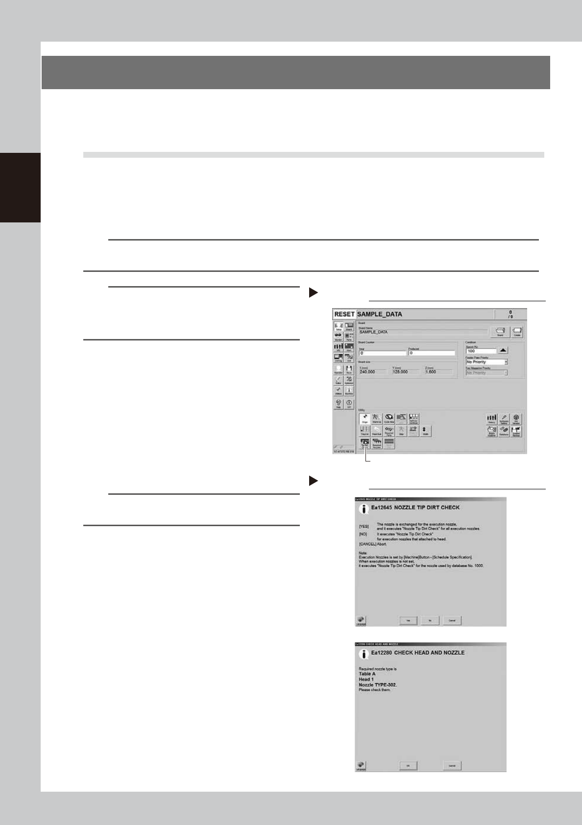
Press the [Tip Dirt Check] button.
Press the [Tip Dirt Check] button on the
[Setup] screen.
54200-L1-10
3
Select the item to be executed.
After checking the displayed message,
select the desired button.
n
When [Yes] was selected
Performs auto nozzle change and checks all relevant
nozzles.
n
When [No] was selected
Checks relevant nozzles of all nozzles currently
attached to the head.
54201-L1-10
4
Check the message.
Check the message, and when it is “NG”,
clean the nozzle by referring to "2.1 Cleaning
the nozzle air path" in Chapter 3. In case of
the FNC nozzle, clean the nozzle by referring
to "2.2 Cleaning FNC nozzles" in Chapter 3.
Selecting the item to be executed
Step 3
When [No] was selected
Pressing the [Check Nozzles] button
Step 2
[Tip Dirt Check] button
2-3
2
Daily maintenance items
n
How to check for clogged nozzles (on the [Unit]-[Head] screen)
The term "clogged nozzle" used here indicates that material such as solder is adhering to the nozzle hole, causing a rise
in negative pressure even if no component is being picked up by the nozzle. This state might cause problems such as
component mounting errors. The following describes the checking procedure for clogged nozzles using Type 302A
nozzles as an example.
n
NOTE
The vacuum level when nozzle is open, which is the criterion for clogged nozzle, varies depending on the nozzle types.
See the next page for the vacuum level when nozzle is open other than Type 302A nozzle.
e
1
Attach the nozzle.
Press the emergency stop button, and
attach Type302A(F) nozzle (in case of FNC,
302F nozzle) to all heads.
If the machine is equipped with a nozzle
station, press the [Nozzle Change] button to
replace the nozzles.
54204-L1-10
2
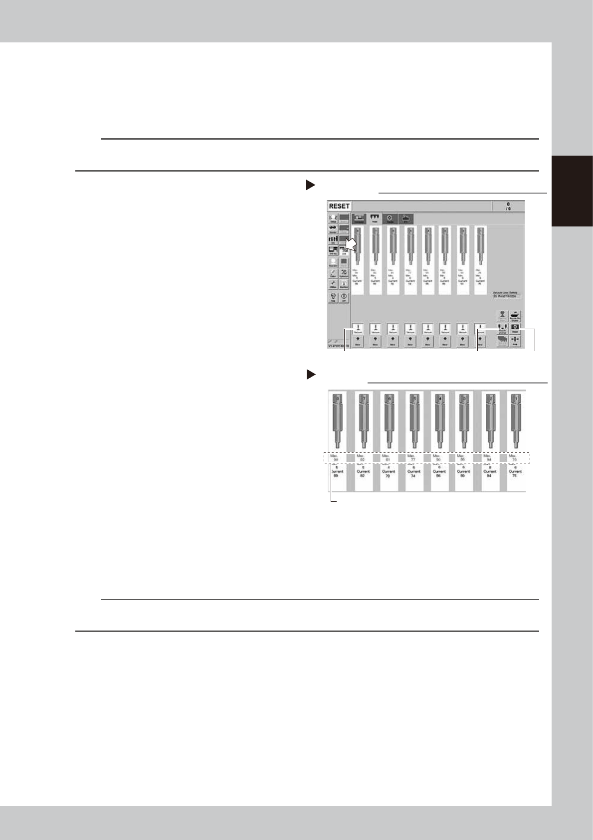
Reset the numerical figure.
Open the [Unit] - [Head] screen. Then press
the [Reset] button on the lower right of the
screen to reset the pickup level values.
3
Generate negative pressure.
On the [Unit] - [Head] screen, set the
[Vacuum] buttons for all heads to ON. When
this value starts rising, wait 5 to 10 seconds
and set to OFF.
4
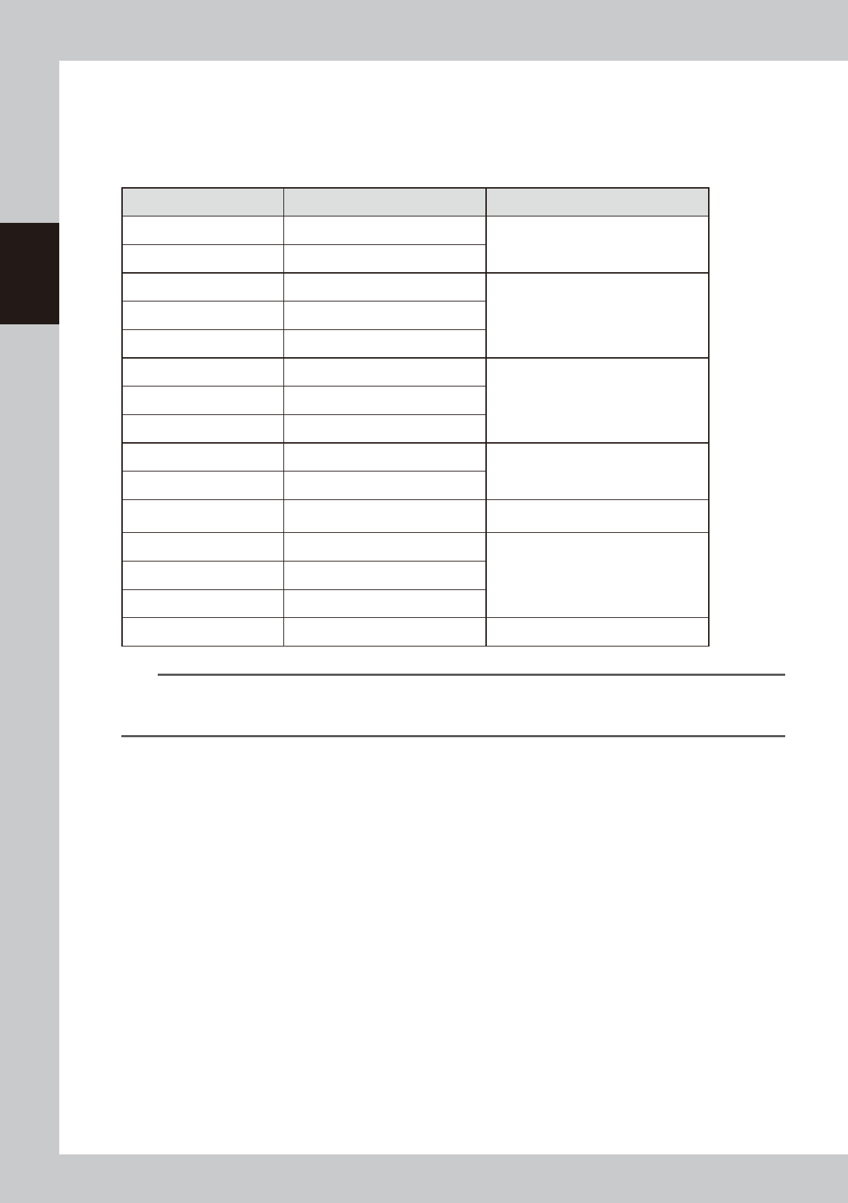
Check the vacuum levels.
Read the value of the “Maximum value”
displayed in red on the screen of the head.
It is a normal range when the read value is
80 to 120 or below (in case of 302F, 90 to
130).
When the number is above the range, the
nozzle hole may be dirty, clean the nozzle
by referring to "1.1 Inspecting and cleaning
the nozzles" in Chapter 3.
In case of the FNC nozzle, clean the nozzle
by referring to "2.2 Cleaning FNC nozzles" in
Chapter 3 also.
54205-L1-10
n
NOTE
If a correct value cannot be obtained after cleaning even after performing steps 1 to 4, then the interior of the spline
shaft might be dirty.
Negative pressure generation
Step 1 to 3
[Nozzle Change] button[Vacuum] button [Reset] button
Negative pressure check
Step 4
Max value
2-4
2
Daily maintenance items
1.1.1 Vacuum level when nozzle is open
The table below shows the vacuum level measured when each nozzle is open.
The values might differ slightly depending on the air source and operating conditions. Use these values for
reference during maintenance.
n
Standard vacuum level when nozzle is open
Nozzle Standard value when nozzle is open Remarks
Type301A 160 to 200
Standard nozzle
Type302A 80 to 120
Type311A 180 to 210
Narrow-pitch nozzleType312A 140 to 180
Type313A 60 to 100
Type303A/Type314A* 50 to 90
Standard & Narrow-pitch common nozzleType304A/Type315A* 40 to 80
Type305A/Type316A* 40 to 80
Type301F 160 to 200
Index nozzle
(Standard nozzle)
Type302F 90 to 130
Type303F 60 to 100
Index nozzle
(Standard & Narrow-pitch common nozzle)
Type311F 160 to 200
Index nozzle
(Narrow-pitch nozzle)
Type312F 90 to 130
Type313F 60 to 100
No nozzle 40 to 80
n
NOTE
The nozzle holes of the nozzles marked with an asterisk are larger than those of other nozzles. If a nozzle marked with
an asterisk exceeds its standard value shown above, the air path in the head (spline shaft, etc.) may be
contaminated.