YS100_Mainte_E.pdf - 第83页
3-18 3 Periodic maintenance items 2.2.3 Cleaning the FNC locate pin Inside the spline shaft of each FNC head, a locate pin (or locate pin) is used to loc k the rotation of the FNC nozzle assembly when the selected nozzle…
3-17
3
Periodic maintenance items
r
Lubricate the bevel gear and shaft.
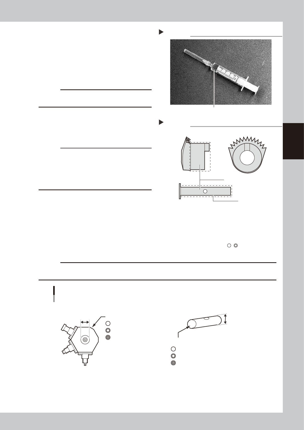
Using the lubrication syringe for nozzle
padding part and turbine oil (VG32), apply
one drop of oil at the inner side of bevel
gear and shaft respectively, and then
spread it with your finger.
53326-L1-10
53327-L1-10
c
CAUTION
Do not lubricate the bevel gear section, as foreign
matter may get caught in the gear.
t
Reassemble the FNC nozzle
assembly.
Use the Phillips screwdriver to reassemble
the nozzles onto the nozzle block.
c
CAUTION
Attach the nozzle where it was removed.
The screwdriver bit size may slightly differ between
manufacturers. Use the screwdriver that matches the
recessed pattern on the screw head.
Take care not to lose the small spring inserted in the
spring-action nozzle.
n
Precautions when replacing the bevel gear shaft (SHAFT_1)
Caution is required when replacing only the bevel gear shaft (SHAFT_1) during maintenance since a nozzle assembly and
SHAFT_1 must be used in the correct combination. There are 3 grades each of nozzle assemblies and SHAFT_1
depending on the hole inner diameter and shaft outer diameter. They are identified by marks ( , , etc.) as shown
below. Always use the correct combination of a nozzle assembly and SHAFT_1 which have the same mark.
c
CAUTION
If the nozzle assembly and SHAFT_1 combination is incorrect, the nozzles may operate erroneously or vacuum leaks
may occur during component pickup.
∅4mm
∅4mm
∅4mm
KV8-M71R1-10X ∅4mm
KV8-M71R1-20X ∅4mm
KV8-M71R1-30X ∅4mm
NOZZLE ASSY (nozzle assembly)
There are 3 grades depending on the hole inner diameter.
ID mark
SHAFT_1
There are 3 grades depending on the outer diameter.
ID mark
Nozzle assembly and SHAFT_1 combination
53328-L1-00
Lubrication syringe for nozzle padding part
Step 14
Turbine oil (VG32)
Lubrication points on bevel gear
Step 14
Shaft
Lubricate with one drop of oil.
3-18
3
Periodic maintenance items
2.2.3 Cleaning the FNC locate pin
Inside the spline shaft of each FNC head, a locate pin (or locate pin) is used to lock the rotation of the FNC
nozzle assembly when the selected nozzle points downwards. If dust or grime adheres to this locate pin,
component pickup or mount errors tend to occur. Although depending on the operation time, we recommend
cleaning the locate pin at the time when you take apart and clean the FNC nozzle assembly.
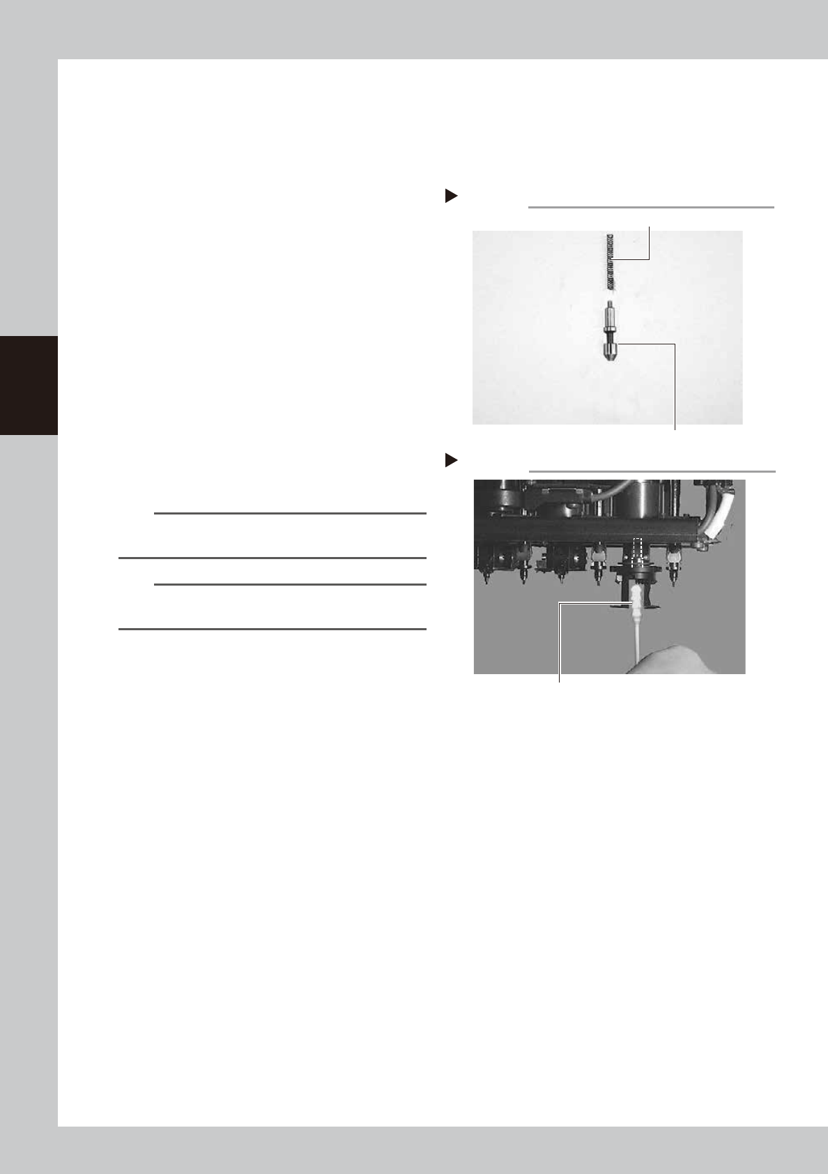
1
Clean the FNC locate pin parts.
Wipe the dirt on the FNC locate pin and
spring with a cleaning cloth moistened with
alcohol.
53329-L1-10
2
Clean the FNC locate pin insertion
hole.
1. Blow air into the air path of the FNC
locate pin insertion section of the spline
shaft with the air blow tool (option).
2. Wipe inside the FNC locate pin insertion
section thoroughly with a spiral-tip cotton
swab moistened with alcohol.
3. After cleaning, check it is completely
clean.
53330-L1-00
n
NOTE
Wipe and clean to the end of the FNC locate pin
insertion section.
n
NOTE
Use spiral-tip cotton swabs (thickness: 4mm or less) that
are commercially available.
3
Lubricate the FNC locate pin.
Using the lubrication syringe for nozzle
padding part and turbine oil (VG32), apply
one to two drops of oil on the FNC locate
pin, and then spread them with your finger.
4
Reinstall the FNC locate pin and
spring.
Advance to the next section "2.2.4
Reassembling the FNC nozzle assembly".
FNC locate pin and spring removed from head
Step 1
FNC locate pin
Spring
Cleaning the FNC locate pin insertion section
Step 2
Wipe with cotton swab/bud moistened with alcohol.
3-19
3
Periodic maintenance items
2.2.4 Reassembling the FNC nozzle assembly
When finished cleaning the FNC nozzle assembly and FNC locate pin, reassemble them as explained below.
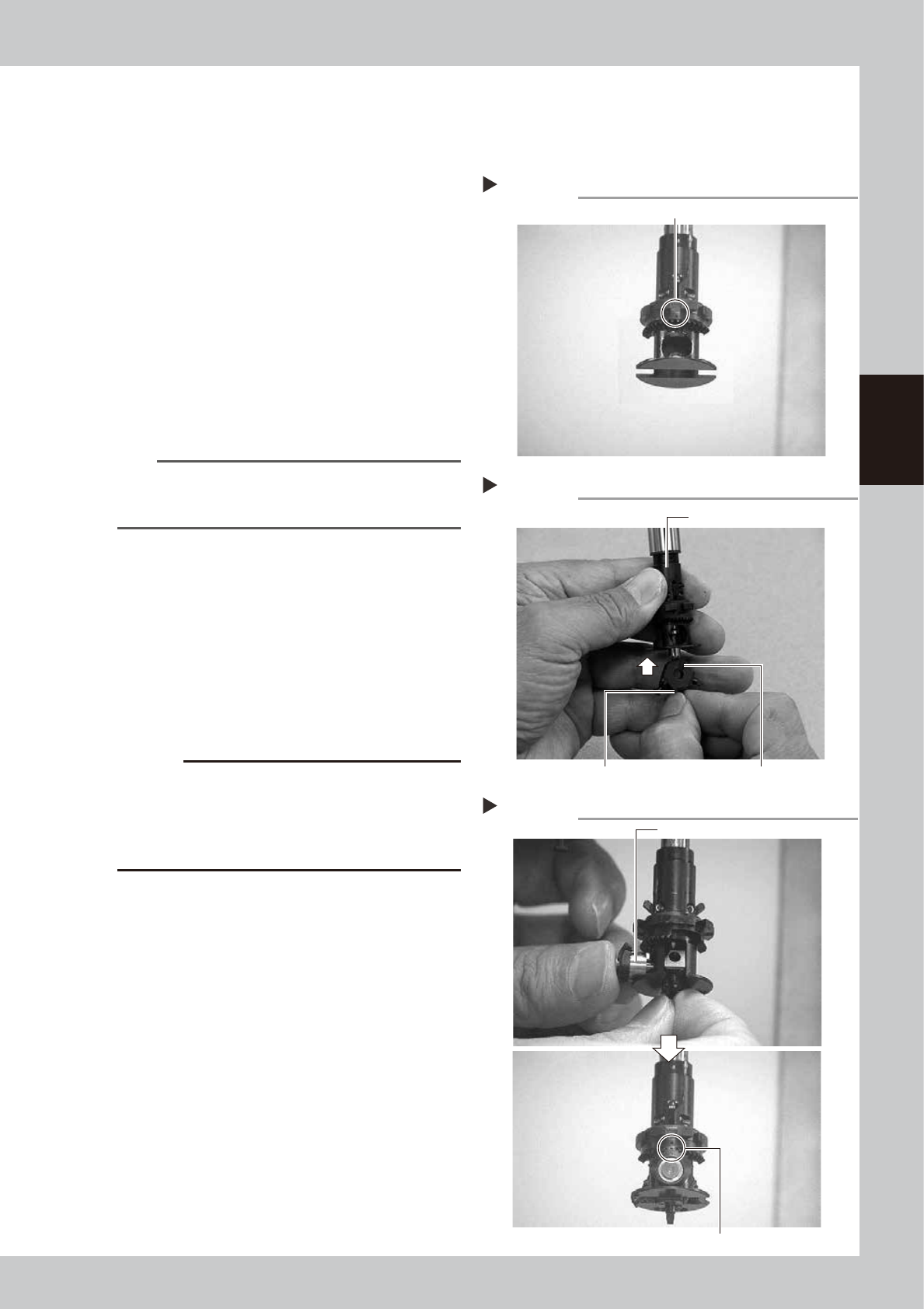
1
Rotate the spline shaft so the mark
in the middle of the index holder
faces the front.
53331-L1-00
2
Reassemble the FNC nozzle
assembly.
Insert, in order, the spring, FNC locate pin
and FNC nozzle assembly into the holder. At
this point, hold the FNC nozzle assembly with
the cutout facing towards the front and
Type 302F nozzle pointing downwards, and
insert each part up into the index holder.
53332-L1-00
n
NOTE
Before inserting the FNC locate pin, make sure that the
small cams above the index holder are retracted
upwards.
3
Insert the bevel gear and shaft into
the center of the FNC nozzle
assembly.
While slightly pressing the FNC nozzle
assembly up, insert the bevel gear and shaft
into the center hole of the FNC nozzle
assembly from the front, and align the mark
on the bevel gear with the mark on the
index holder.
53333-L1-00
c
CAUTION
Reassemble the nozzle assembly, bevel gear and shaft
in their original combination for each FNC head, without
mixing them with parts for other heads. If this
combination is changed, the bevel gear may not rotate
smoothly or the pickup vacuum level may drop.
Positioning so the mark faces the front
Step 1
This mark should face the front.
Inserting the FNC nozzle assembly
Step 2
Type 302F nozzle should be pointed downwards. Cutout
Index holder
Inserting the bevel gear and shaft
Step 3
Insert the shaft.
Align marks with each other.