YS100_Mainte_E.pdf - 第85页
3-20 3 Periodic maintenance items 4 Secure the FNC nozzle assembly . 1. Turn the index holder so that the bevel gear faces the opposite side. 2. Align the sur face of the bevel gear shaft horizontally and slide the stopp…
3-19
3
Periodic maintenance items
2.2.4 Reassembling the FNC nozzle assembly
When finished cleaning the FNC nozzle assembly and FNC locate pin, reassemble them as explained below.
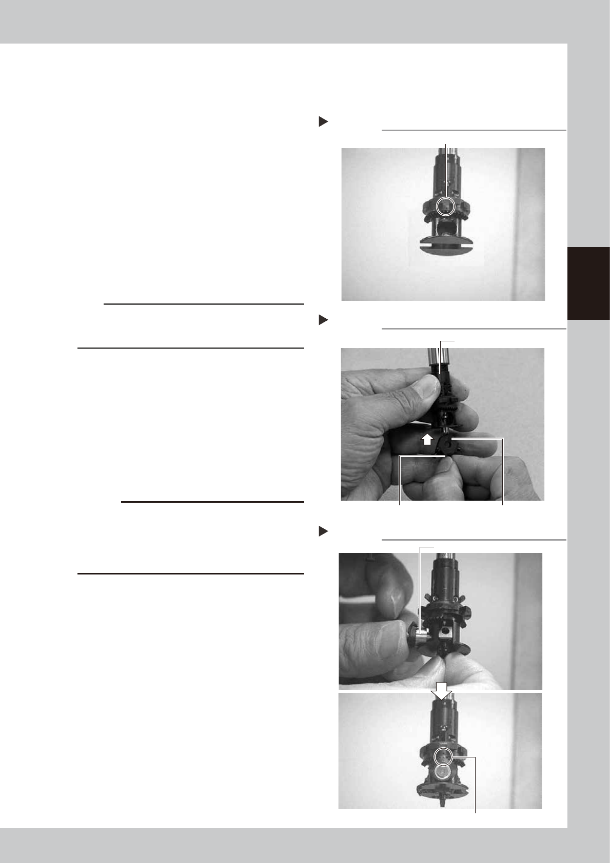
1
Rotate the spline shaft so the mark
in the middle of the index holder
faces the front.
53331-L1-00
2
Reassemble the FNC nozzle
assembly.
Insert, in order, the spring, FNC locate pin
and FNC nozzle assembly into the holder. At
this point, hold the FNC nozzle assembly with
the cutout facing towards the front and
Type 302F nozzle pointing downwards, and
insert each part up into the index holder.
53332-L1-00
n
NOTE
Before inserting the FNC locate pin, make sure that the
small cams above the index holder are retracted
upwards.
3
Insert the bevel gear and shaft into
the center of the FNC nozzle
assembly.
While slightly pressing the FNC nozzle
assembly up, insert the bevel gear and shaft
into the center hole of the FNC nozzle
assembly from the front, and align the mark
on the bevel gear with the mark on the
index holder.
53333-L1-00
c
CAUTION
Reassemble the nozzle assembly, bevel gear and shaft
in their original combination for each FNC head, without
mixing them with parts for other heads. If this
combination is changed, the bevel gear may not rotate
smoothly or the pickup vacuum level may drop.
Positioning so the mark faces the front
Step 1
This mark should face the front.
Inserting the FNC nozzle assembly
Step 2
Type 302F nozzle should be pointed downwards. Cutout
Index holder
Inserting the bevel gear and shaft
Step 3
Insert the shaft.
Align marks with each other.
3-20
3
Periodic maintenance items
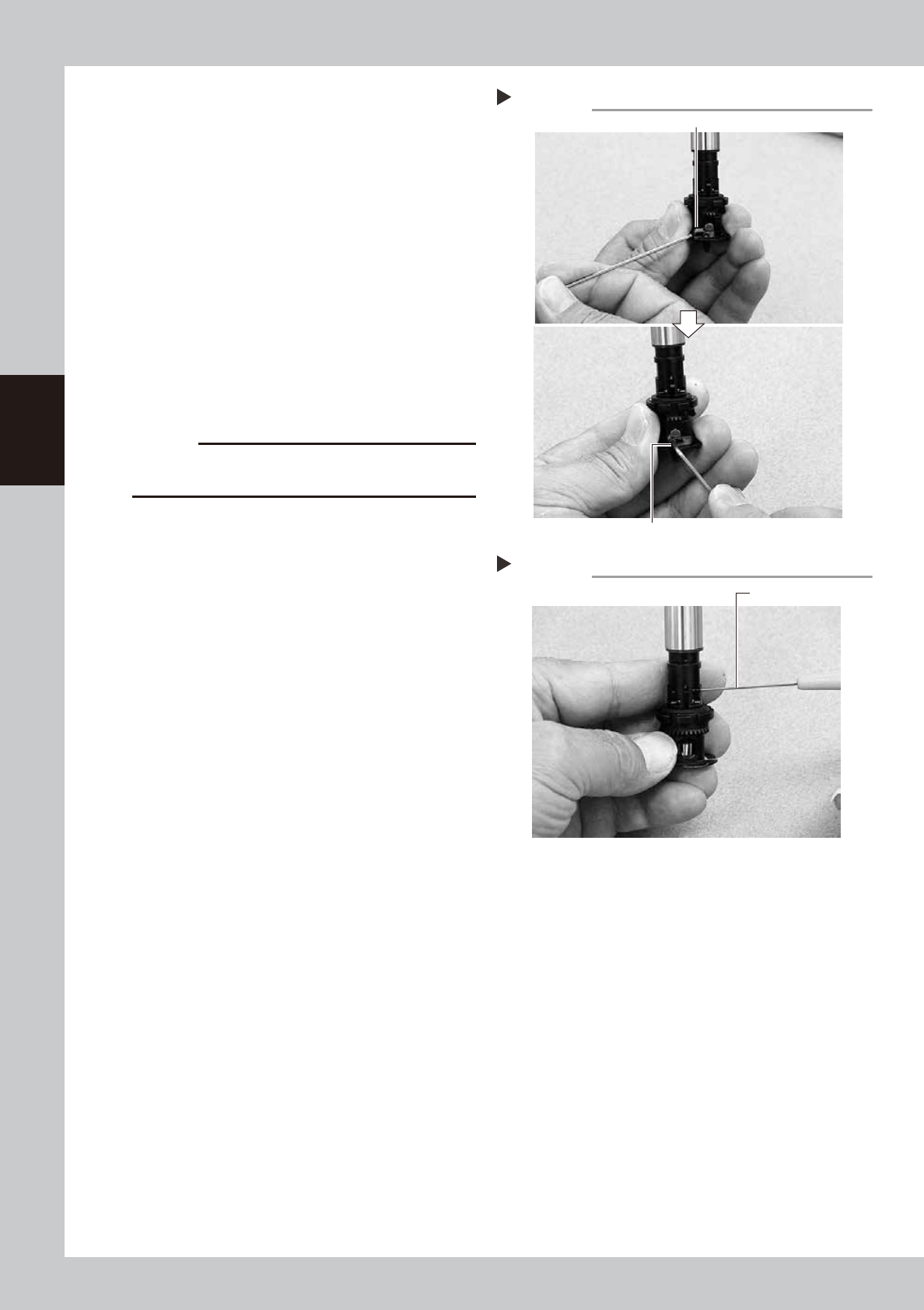
4
Secure the FNC nozzle assembly.
1. Turn the index holder so that the bevel
gear faces the opposite side.
2. Align the surface of the bevel gear shaft
horizontally and slide the stopper block
back to the original position. Then tighten
the bolt with the M1.5 hex wrench to
secure the stopper block.
53334-L1-00
3. Rotate the spline shaft so the bevel gear
faces the front. While the spline shaft is
pulled out, fix the set screw for the locate
pin cam stopper with the special hex
wrench (0.7) or a hex wrench (0.7)
commercially available.
53335-L1-00
c
CAUTION
Be cautious not to tighten the set screw for locate pin
cam stopper too tight, because the size is small.
Securing the FNC nozzle assembly
Step 4-2
Position the flat face of shaft horizontally.
Secure the stopper block with the hex wrench.
Tightening the set screw for locate pin cam
Step 4-3
Dedicated hex wrench
3-21
3
Periodic maintenance items
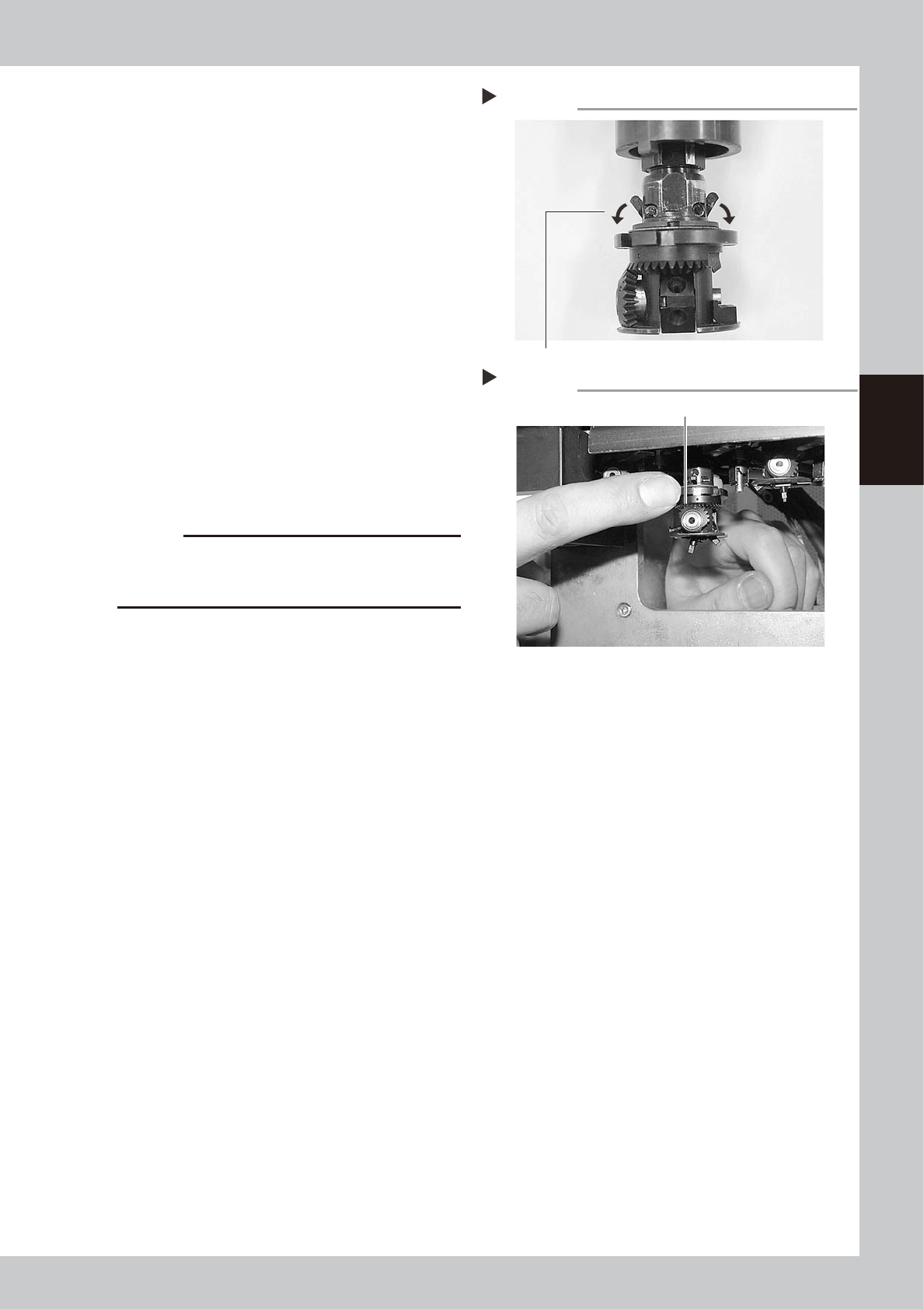
5
Check the movement after
reassembly.
1. After reassembling the FNC nozzle
assembly, press the [Head] button on the
[Unit]-[Head] screen to lower the
reassembled head.
2. Lower the FNC locate pin cam.
Lowering this cam releases the FNC
locate pin, allowing you to rotate the
bevel gear by hand.
53336-L1-00
3. With the cam still lowered, check that
rotating the larger bevel gear also
rotates the smaller bevel gear smoothly.
53337-L1-00
6
Check the nozzle change
movement.
On the [Unit]-[Head] screen, press the
[Nozzle Change] button to check that each
nozzle changes normally.
c
CAUTION
On machines with an optional nozzle station, cancel
emergency stop and check safety before performing
nozzle change.
Releasing the FNC locate pin
Step 5-2
Lower the cam.
Checking the bevel gear movement
Step 5-3
Rotate the larger bevel gear to check movement.