YS100_Mainte_E.pdf - 第86页
3-21 3 Periodic maintenance items 5 Check the mo vement after reassembly . 1. After reassembling the FNC nozzle assembly, press the [Head] button on the [Unit]-[Head] screen to lower the reassembled head. 2. Lower the FN…
3-20
3
Periodic maintenance items
4
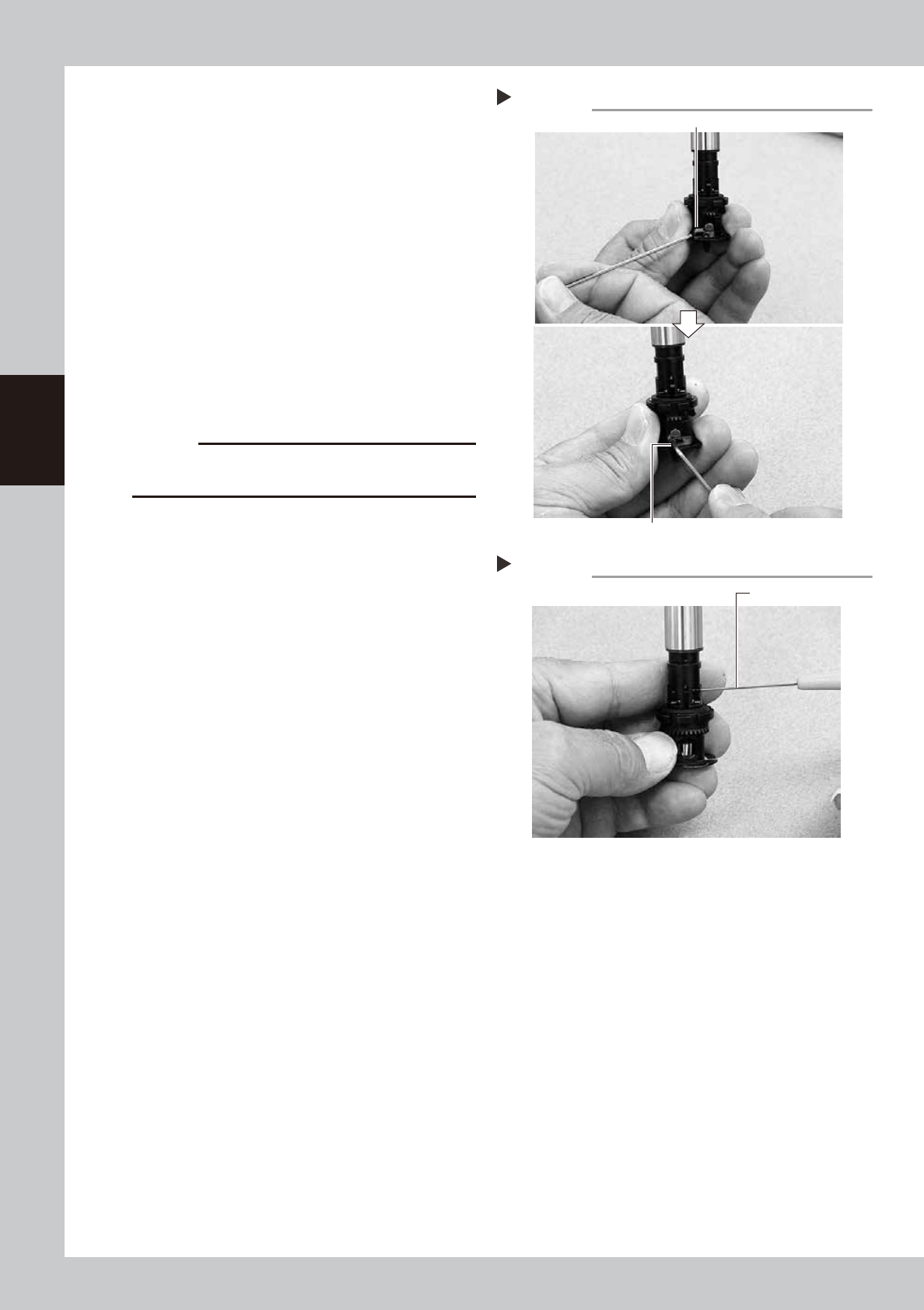
Secure the FNC nozzle assembly.
1. Turn the index holder so that the bevel
gear faces the opposite side.
2. Align the surface of the bevel gear shaft
horizontally and slide the stopper block
back to the original position. Then tighten
the bolt with the M1.5 hex wrench to
secure the stopper block.
53334-L1-00
3. Rotate the spline shaft so the bevel gear
faces the front. While the spline shaft is
pulled out, fix the set screw for the locate
pin cam stopper with the special hex
wrench (0.7) or a hex wrench (0.7)
commercially available.
53335-L1-00
c
CAUTION
Be cautious not to tighten the set screw for locate pin
cam stopper too tight, because the size is small.
Securing the FNC nozzle assembly
Step 4-2
Position the flat face of shaft horizontally.
Secure the stopper block with the hex wrench.
Tightening the set screw for locate pin cam
Step 4-3
Dedicated hex wrench
3-21
3
Periodic maintenance items
5
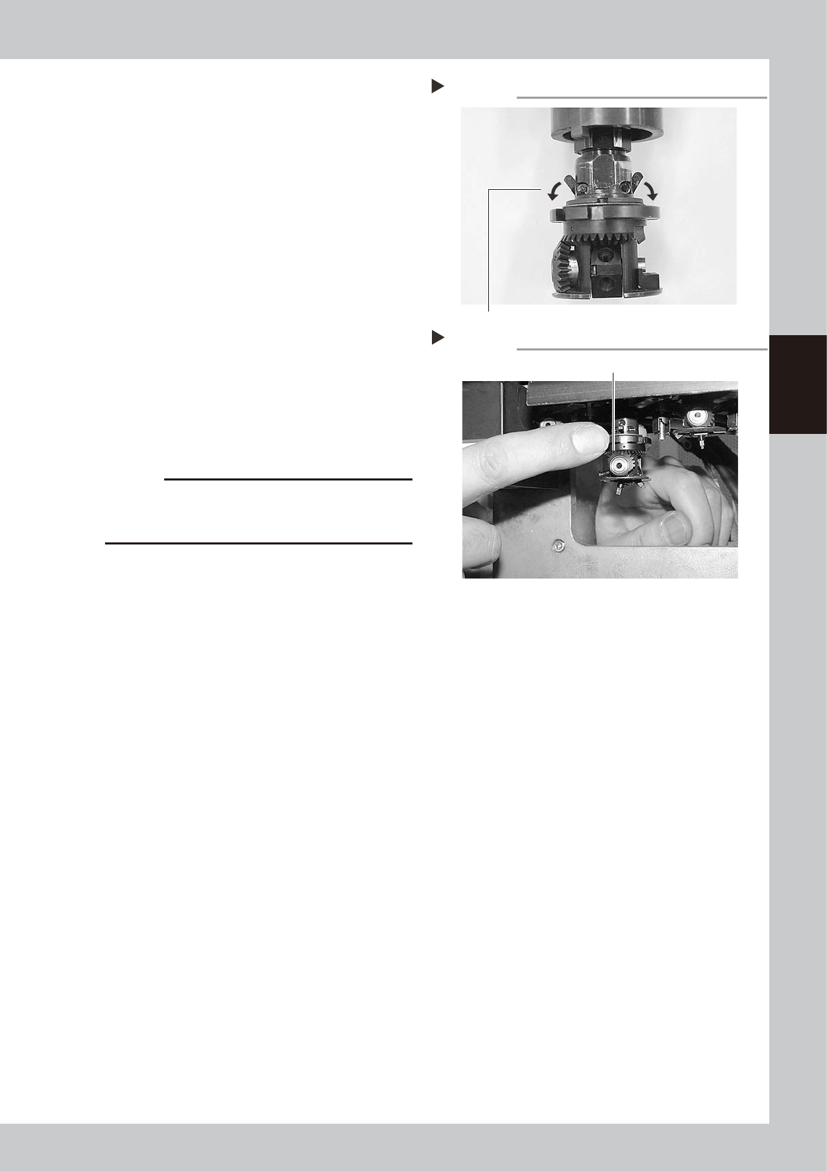
Check the movement after
reassembly.
1. After reassembling the FNC nozzle
assembly, press the [Head] button on the
[Unit]-[Head] screen to lower the
reassembled head.
2. Lower the FNC locate pin cam.
Lowering this cam releases the FNC
locate pin, allowing you to rotate the
bevel gear by hand.
53336-L1-00
3. With the cam still lowered, check that
rotating the larger bevel gear also
rotates the smaller bevel gear smoothly.
53337-L1-00
6
Check the nozzle change
movement.
On the [Unit]-[Head] screen, press the
[Nozzle Change] button to check that each
nozzle changes normally.
c
CAUTION
On machines with an optional nozzle station, cancel
emergency stop and check safety before performing
nozzle change.
Releasing the FNC locate pin
Step 5-2
Lower the cam.
Checking the bevel gear movement
Step 5-3
Rotate the larger bevel gear to check movement.

3-22
3
Periodic maintenance items
2.3 Inspecting ball screws and guides of each axis
Inspect the ball screws and the guides on the X, Y, W, and push-up axes. Checkpoints are listed below.
An anti grease splatter cover is attached to the X and Y axes. Remove these covers when inspecting the ball
screws and guides.
TIP
See "3.1 Cleaning and greasing the X and Y axis" described later on for detaching or attaching the anti grease
splatter cover.
TIP
See "3.1 Cleaning and greasing the X and Y axis", "3.2 Cleaning and greasing the push-up axis (PU axis)" and "5.2
Cleaning and lubricating the W-axis" in this chapter, and "Chapter 5 Lubrication points and schedule" for positions of
ball screws and guides of each axis.
Checkpoints
1. Any foreign objects adhering to the ball screws and guides?
Check if any fallen chips have adhered to the ball screws and/or guides.
2. Do the ball screws and guides have the correct amount of grease?
Check if grease has flowed off or splattered in the air failing to adhere. Also check if grease has discolored or hardened.
e
3. Any abnormal sounds from the ball screws?
Press the emergency stop button. Check for any abnormal sounds by pressing the X-axis or Y-axis back and forth
manually.
Countermeasures
1. Ball screws and guides may be damaged when chips and other material bite into them. If chips are adhering, wipe
them off along with the grease or remove with tweezers, etc.
2. Apply grease referring to "3.1 Cleaning and greasing the X and Y axis", "3.2 Cleaning and greasing the push-up axis (PU
axis)", "5.2 Cleaning and lubricating the W-axis" and "Chapter 5 Lubrication points and schedule" in this chapter
described later on.
3. Contact YAMAHA sales representative when abnormal sounds occur even after trying the countermeasures in the above
steps 1 and 2.