YS100_Mainte_E.pdf - 第89页
3-24 3 Periodic maintenance items 3 Clean the ball screws. 1. Grasp the carrying handle to move each axis to one end. 2. Wipe away the old grease and dirt from the ball screw with a lint-free cloth (for clean room use). …
3-23
3
Periodic maintenance items
3. Two-month inspection
3.1 Cleaning and greasing the X and Y axis
This section describes how to clean and grease the X and Y axes. See "Chapter 5 Lubrication points and
schedule" for lubrication points and lubrication form. Prepare a grease gun and specified grease (NSL).
c
CAUTION
For information on the use of grease, read the caution items for handling in "Safety instructions" and chapter 1, "2.2.2
Lubricating tools and grease".
c
CAUTION
If abnormal sound is heard from the X and Y axis ball screws or guides, contact YAMAHA sales representative.
Disassembly and cleaning of the ball screws or guides by the user will void the warranty.
3.1.1 Cleaning and greasing the X and Y axis ball screws
e
1
Prepare for maintenance work.
1. Press the emergency stop button and
then open the machine safety cover.
2. If the machine is equipped with a
carriage, remove the carriage to easily
access to the X axis and Y axis
2
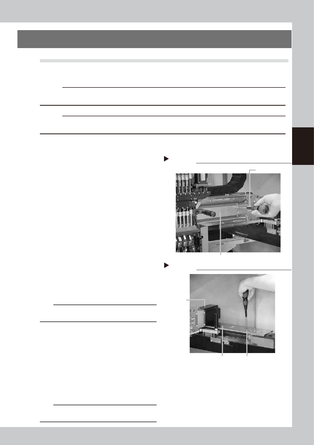
Remove the ball screw covers.
Remove the X, Y1 and Y2 axis ball screw
covers.
X-axis
1. Use a Phillips screwdriver to remove the
screws mounting the left side of the ball
screw cover.
2. Move the head unit all the way to the
left side and remove the screws
mounting the right side of the ball screw
cover.
3. Remove the ball screw cover by pulling it
to the right.
53338-L1-00
TIP
When reattaching the X-axis ball screw cover, use the
reverse order of the above procedure.
Y1 and Y2 axes
1. Use a Phillips screwdriver to remove the
screws mounting the rear side of the ball
screw cover.
2. Move the head unit all the way to the
rear side and remove the screws
mounting the front side of the ball screw
cover.
3. Remove the ball screw cover by pulling it
to the front.
53339-L1-00
TIP
When reattaching the Y-axis ball screw covers, use the
reverse order of the above procedure.
Removing the X-axis ball screw cover
Phillips screwdriver
Step 2
X-axis ball screw cover
Removing the Y-axis ball screw cover
Y-axis ball screw cover
Step 2
Y-axis ball screw cover
mounting screw
Y-axis motor
3-24
3
Periodic maintenance items
3
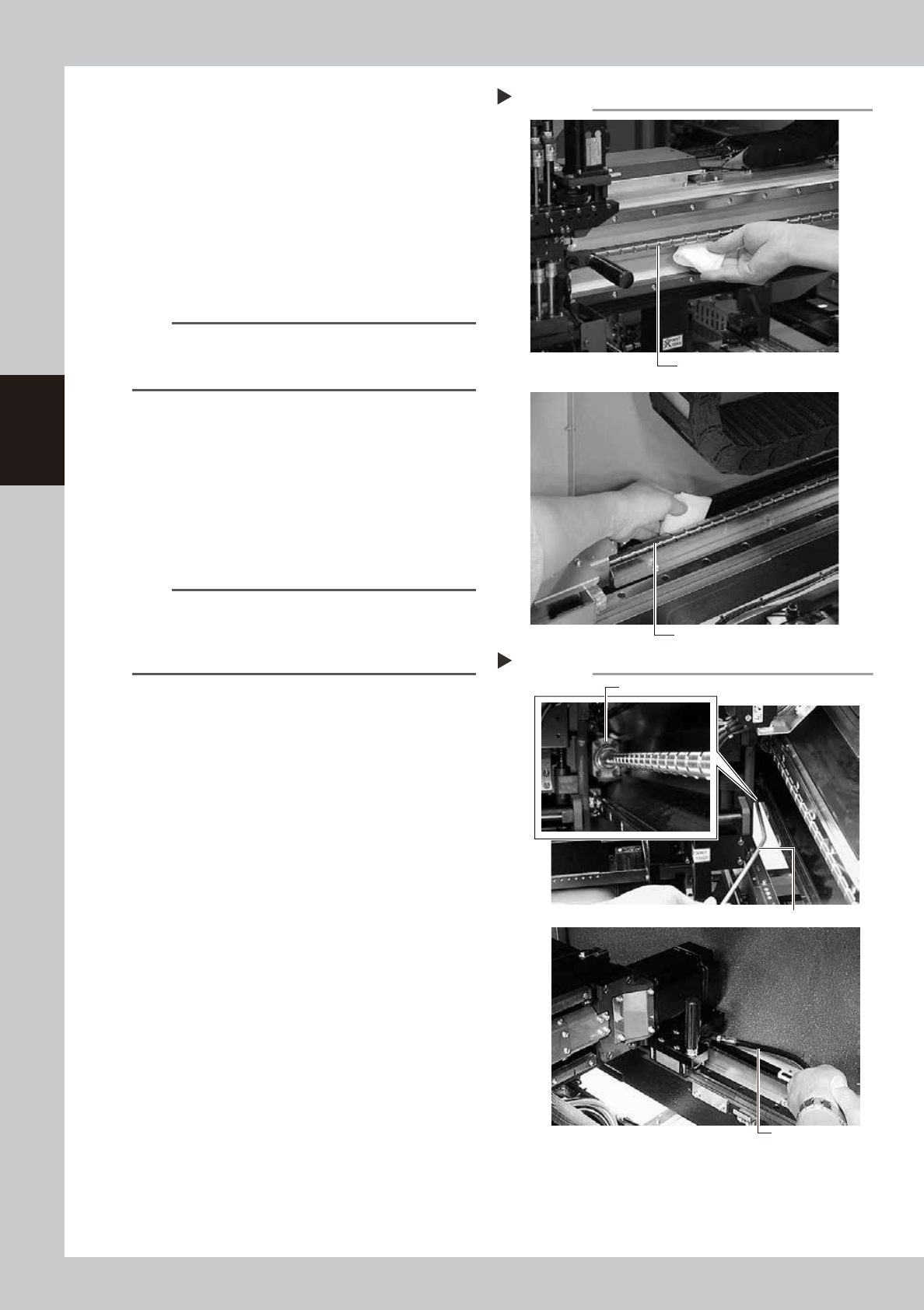
Clean the ball screws.
1. Grasp the carrying handle to move each
axis to one end.
2. Wipe away the old grease and dirt from
the ball screw with a lint-free cloth (for
clean room use).
3. Move the axes to the opposite end and
wipe the opposite side ball screw clean
(X and Y axes).
53340-L1-10
n
NOTE
Carefully wipe the lead grooves of the ball screws
during the cleaning work. Additionally, make sure that
any dirt is not produced.
4
Apply grease to the ball screws.
X-axis, Y-axis
Use the grease gun to supply the specified
grease (NSL) to the grease nipples.
Then move the head back and forth by
hand along each axis and wipe away
excess grease.
53341-L1-10
n
NOTE
The bent type nozzle is necessary for lubrication of the X
axis ball screw, and the flexible type nozzle is necessary
for lubrication of the Y axis ball screw. Make sure to
attach the correct one.
5
Reattach the covers.
Reattach the ball screw covers in the
reverse order of the removal procedures.
Cleaning the ball screws
Step 3
X-axis ball screw
Y-axis ball screw
Greasing the ball screws
Step 4
Grease nipple
Grease gun
Grease gun
X-axis
Y-axis
3-25
3
Periodic maintenance items
3.1.2 Cleaning and greasing the X, Y and W axes guides
e
1
Prepare for maintenance work.
1. Press the emergency stop button and
then open the machine safety cover.
2. If the machine is equipped with a
carriage, remove the carriage to easily
access to the head unit.
2
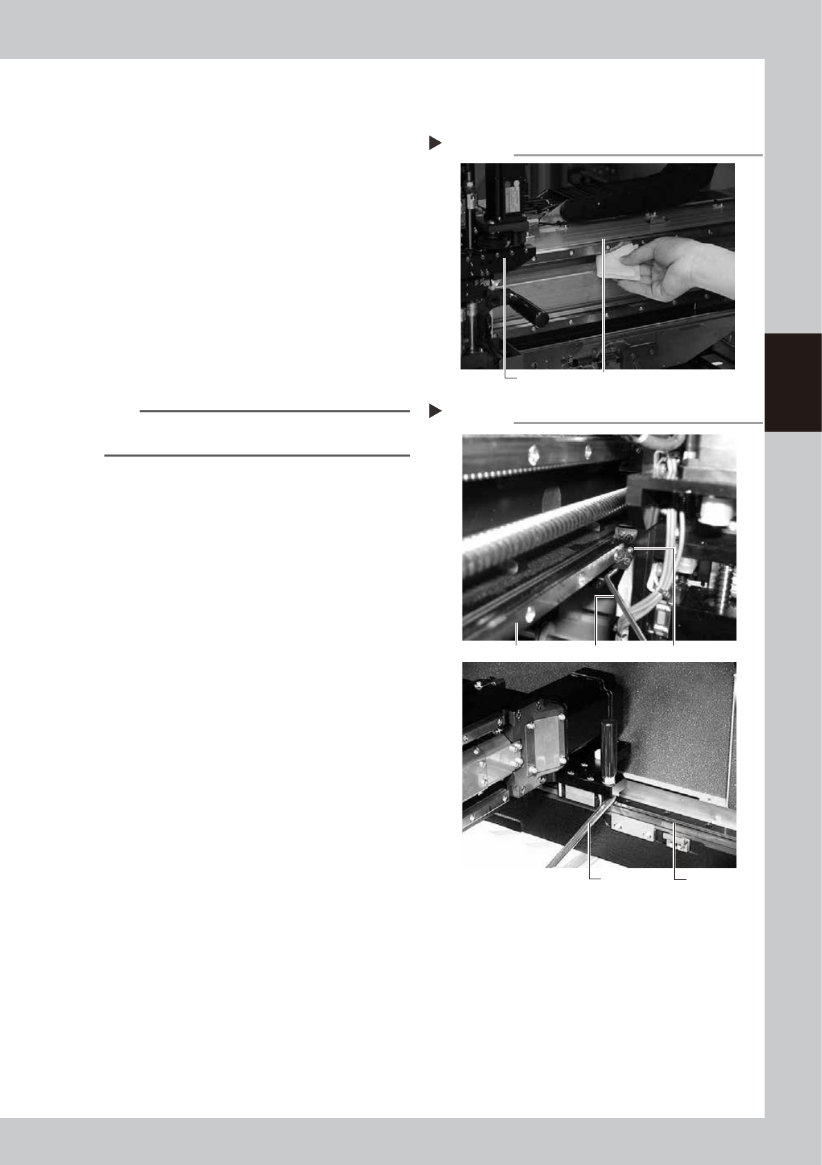
Clean the guides.
1. After moving each axis to the edge,
clean the whole guide with a lint-free
cloth that does not raise dust.
2. Move the axis to the opposite side and
wipe the opposite side guides (X-axis and
Y-axis).
53342-L1-00
n
NOTE
Wipe away thoroughly the old grease in the grooves of
the guide rails.
3
Apply new grease to the guide rails.
1. X axis
Set the bent type nozzle on the grease
gun, and inject the specified grease
(NSL) into the grease nipple for X axis
guide.
The grease nipples are located behind
the head assembly, two each on the
right and left at the positions (heights) of
the upper and lower guides (total of 4
places).
2. Y1 and Y2 axes
Set the standard type nozzle on the
grease gun, and inject the specified
grease (NSL) into the grease nipple for Y
axis guide.
The grease nipples are located on the
front and back sides of the slider on
each Y-axis guide (total of 4 places).
53343-L1-00
4
Remove excess grease.
After moving the axis left and right (X-axis)
or back and forth (Y-axis) manually a few
times, wipe away excess grease.
Cleaning the guides
Step 2
Guide rail Wipe with cleaning cloth or paper towel.
Greasing the guide
Step 3
Y-axis guide
Grease gun
Grease gunX-axis guide
Grease nipple