YS100_Mainte_E.pdf - 第91页
3-26 3 Periodic maintenance items 3.2 Cleaning and greasing the push-up axis (PU axis) T he push-up axis prevents flexing or warping of the board during clamping. It is important as it prevents depressing of the board du…
3-25
3
Periodic maintenance items
3.1.2 Cleaning and greasing the X, Y and W axes guides
e
1
Prepare for maintenance work.
1. Press the emergency stop button and
then open the machine safety cover.
2. If the machine is equipped with a
carriage, remove the carriage to easily
access to the head unit.
2
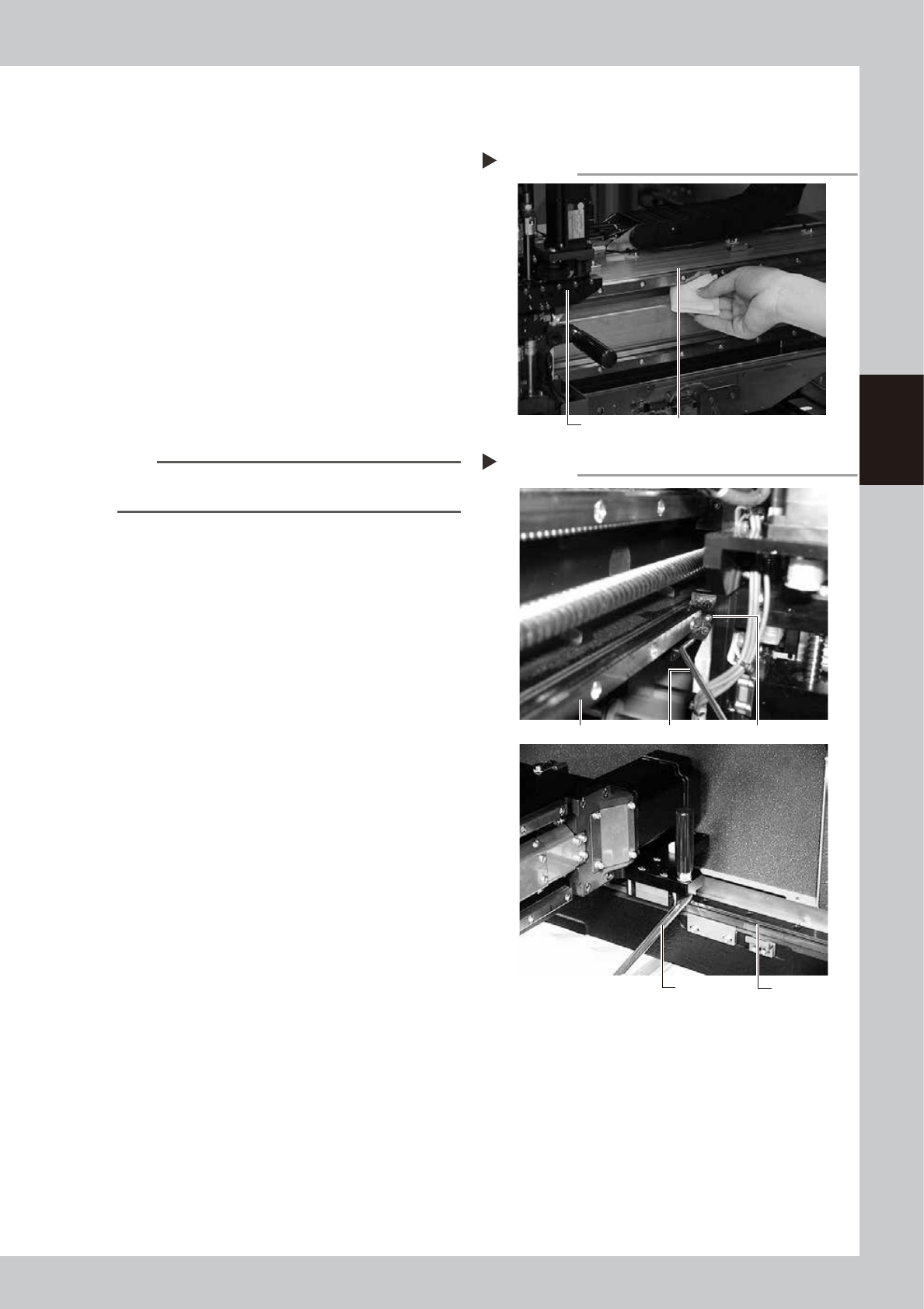
Clean the guides.
1. After moving each axis to the edge,
clean the whole guide with a lint-free
cloth that does not raise dust.
2. Move the axis to the opposite side and
wipe the opposite side guides (X-axis and
Y-axis).
53342-L1-00
n
NOTE
Wipe away thoroughly the old grease in the grooves of
the guide rails.
3
Apply new grease to the guide rails.
1. X axis
Set the bent type nozzle on the grease
gun, and inject the specified grease
(NSL) into the grease nipple for X axis
guide.
The grease nipples are located behind
the head assembly, two each on the
right and left at the positions (heights) of
the upper and lower guides (total of 4
places).
2. Y1 and Y2 axes
Set the standard type nozzle on the
grease gun, and inject the specified
grease (NSL) into the grease nipple for Y
axis guide.
The grease nipples are located on the
front and back sides of the slider on
each Y-axis guide (total of 4 places).
53343-L1-00
4
Remove excess grease.
After moving the axis left and right (X-axis)
or back and forth (Y-axis) manually a few
times, wipe away excess grease.
Cleaning the guides
Step 2
Guide rail Wipe with cleaning cloth or paper towel.
Greasing the guide
Step 3
Y-axis guide
Grease gun
Grease gunX-axis guide
Grease nipple
3-26
3
Periodic maintenance items
3.2 Cleaning and greasing the push-up axis (PU axis)
The push-up axis prevents flexing or warping of the board during clamping. It is important as it prevents
depressing of the board during component mounting.
The push-up axis also prevents deviations in the component mounting accuracy due to the board depressing
during component mounting. Periodic cleaning and lubricating the push-up axis is required to ensure it
operates correctly.
c
CAUTION
If trouble occurs with the push-up axis, contact YAMAHA sales representative. Disassembly and cleaning of the
push-up axis by the user will void the warranty.
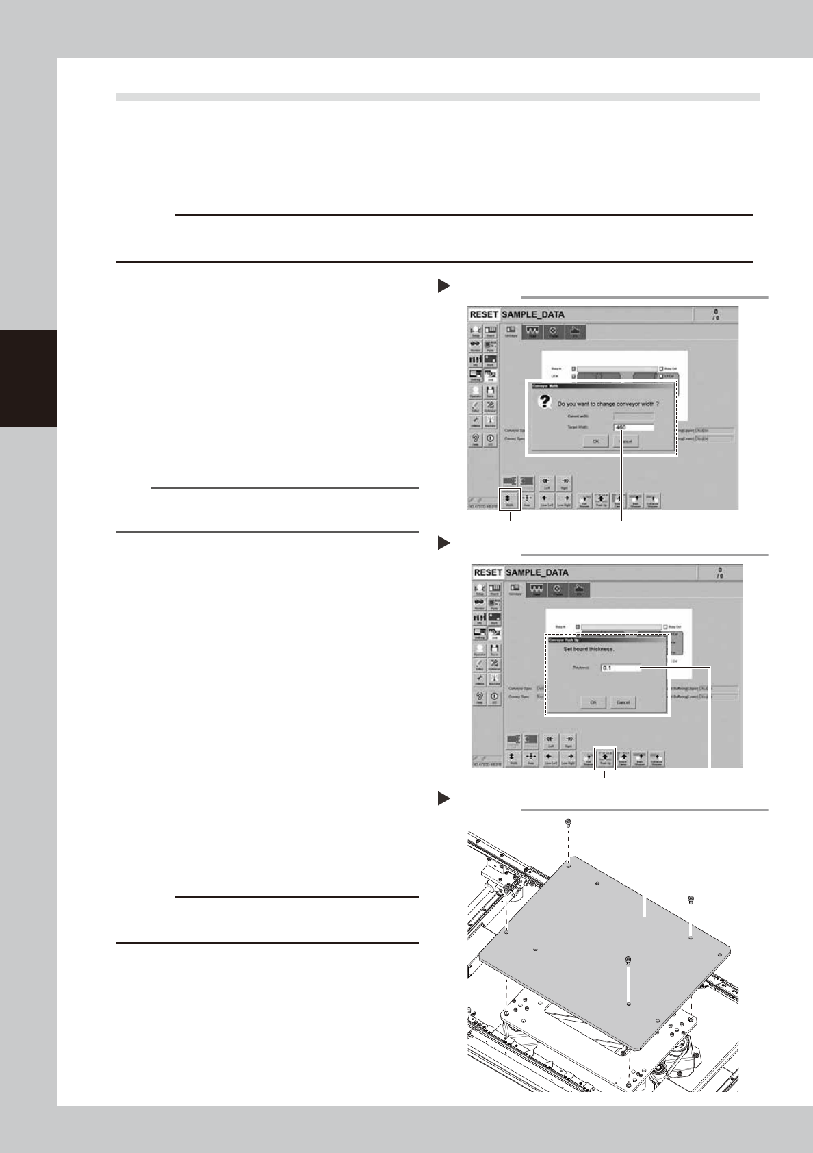
1
Change the conveyor width to its
maximum width.
1. Press the [Conveyor Width] button on the
[Unit] – [Conveyor] screen to display the
“Conveyor Width” screen.
2. Enter the maximum value of the
conveyor width in the “Changed
conveyor width”, press [OK]. The
conveyor is changed to the width that
was just entered.
54304-L1-10
TIP
The maximum conveyor width value is 460 mm or 410
mm in standard specification.
2
Raise the push-up unit.
1. Press the [Push-up] button to display the
“Conveyor Push-up” screen.
2. Enter “0.1 mm” in “Thickness”, and press
the [OK] button. The push-up unit moves
up.
54319-L1-00
e
3
Remove the push-up plate.
1. Press the emergency stop button and
then open the machine safety cover.
2. If the machine is equipped with a
carriage, remove the carriage to easily
access to the push-up axis.
3. Removed the fixed bolts (four locations)
on the push-up plate using the hex
wrench (4) to remove the push-up plate.
53374-L1-00
c
CAUTION
The push-up plate is heavy. Use plenty of caution when
handling.
4
Remove the old grease.
Remove the old grease from the 2 ball
screws and 2 ball guides with lint-free cloth
that does not raise dust.
Changing the conveyor width
Step 1
[width] button Enter the maximum conveyor value
Step 2
Raise the push-up unit
[Push Up] button Enter “0.1 mm”
Removing the push-up plate
Step 3
Push-up plate
3-27
3
Periodic maintenance items
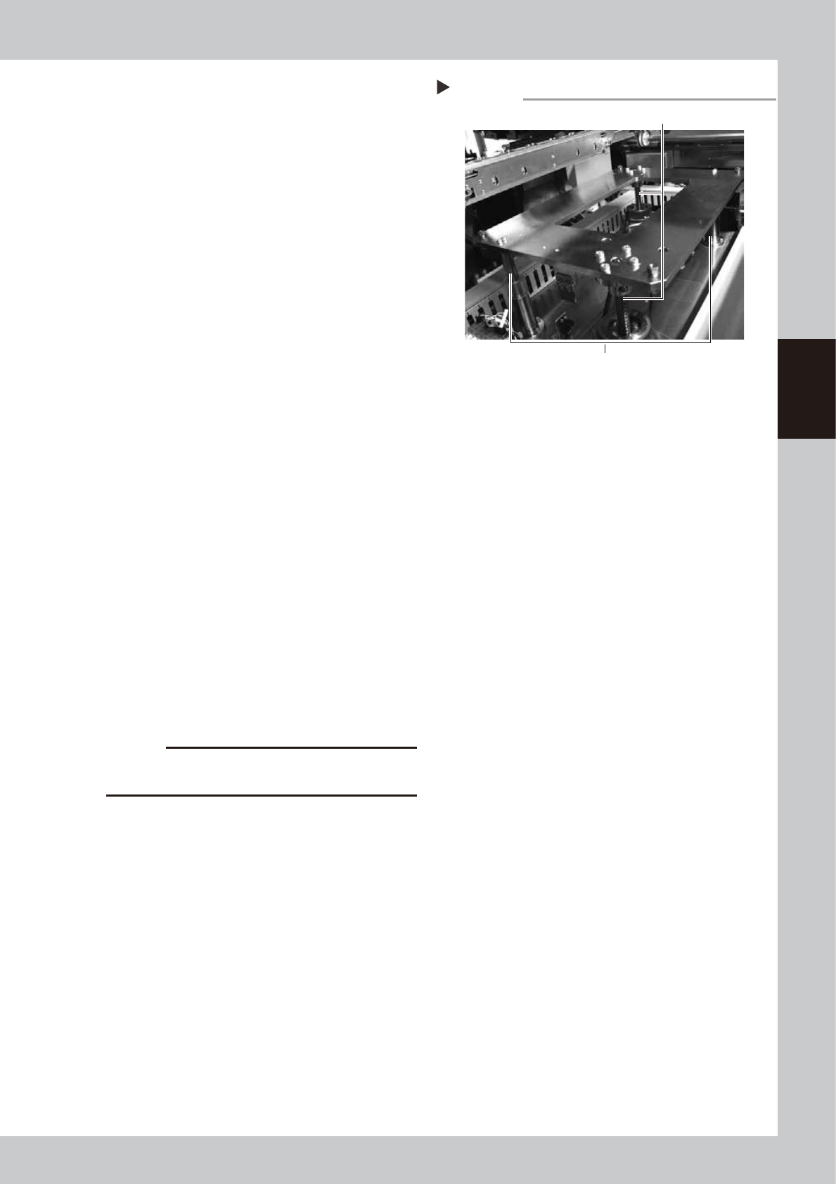
5
Apply the new grease.
Ball screw
Apply as much as 2 cm of specified grease
(NSL) to finger. Rub it evenly into the ball
screw grooves.
Ball guide
Apply as much as 2 cm of specified grease
(NSL) to finger. Coat it evenly on the ball
guides.
53346-L1-00
6
Set the applied grease.
1. Close the machine’s safety cover, and
cancel the emergency stop. If the
machine could be equipped with a
carriage, set the carriage.
2. Press the [Push-up] button to lower the
push-up unit.
3. Press the [Push Up] button again to raise
the push-up unit.
4. Repeat Step 2 and 3 several times to set
the grease. After setting the grease,
leave the push-up unit in the up state.
e
7
Wipe away excess grease.
1. Press the emergency stop button, and
open the machine’s safety cover. If the
machine is equipped with a carriage,
remove the carriage.
2. Wipe the excess grease with lint-free
cloth that does not raise dust.
8
Attach the push-up plate to its
original position.
Attach the push-up plate in the reverse
procedure of step 3.
c
CAUTION
The push-up plate is heavy. Use plenty of caution when
handling.
Applying the grease
Step 5
Ball guides (2 places)
Ball screws (2 places)