00192299-02.pdf - 第104页
2 Retrofitting Instructions: Mechanical Ceramic Substrate Centering HS -50 SIPLACE HS -50 2.7 Checking the Function 01/01 Issue 104 $GMXVWLQJWK H6WRSSHU3RVLWLRQ .H\ A) PCB / subs trate tra nsport d irectio n …
SIPLACE HS-50 2 Retrofitting Instructions: Mechanical Ceramic Substrate Centering HS-50
01/01 Issue 2.7 Checking the Function
103
Å During the following step, keep an eye on the substrate and the closing movement of the X-
centering unit. The substrate is not to raise.
For the corresponding conveyor (processing area), select: PCB onto processing belt 1.
Å If the substrate is lifted when the open centering unit moves upward, you must adjust the
stopper position (see Section 2.7.3).
Å After the lifting table is raised, the x-centering unit close due to the tension spring on the flat
cylinder (no pressure applied, proximity switch signal = 0).
If an error message is displayed, see Section 2.7.4.
Å Select:PCB onto intermediate belt.
The X-centering unit must open before the lifting table moves down (pressure applied, proxim-
ity switch signal = 1
Å Carry out the above-described check on the function and the substrate/stopper position for pro-
cessing belt 2.
Å Select: PCB onto processing belt 2.
Å If necessary correct the stopper position (see Section 2.7.3).
Å Select: PCB onto output belt.
Å If the stopper is in the right position, conduct a trial placement with substrate and check
whether the fiducials of the substrate can be reliably recognized. If necessary, select a different
type of illumination (see User Manual).
2 Retrofitting Instructions: Mechanical Ceramic Substrate Centering HS-50 SIPLACE HS-50
2.7 Checking the Function 01/01 Issue
104
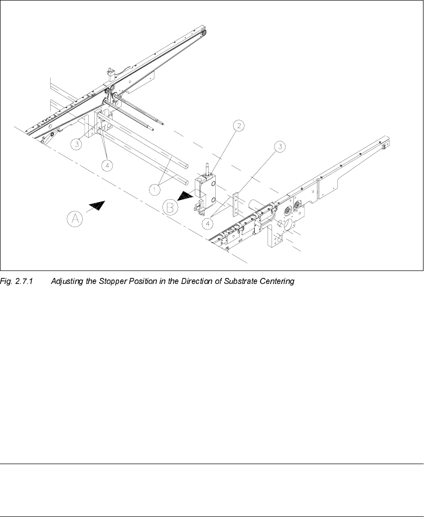
$GMXVWLQJWK H6WRSSHU3RVLWLRQ
.H\
A) PCB / substrate transport direction
B) Direction for adjusting the postion of the stopper
1. Stopper axles (on dual conveyor: continuous axles for belt 2)
2. Stopper assembly
3. Connection rail on fixed and movable side of the conveyor
4. Fastening for the connection rails: 2 socket hex head cap screws M4
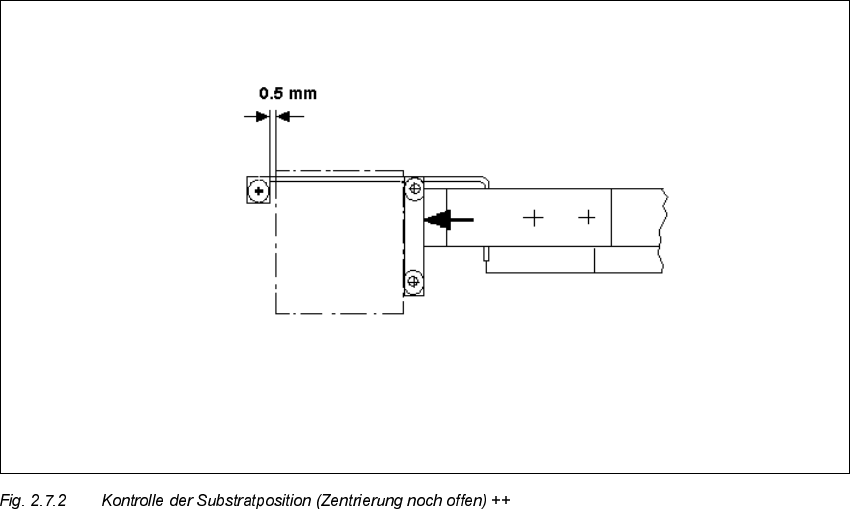
NOTE:
As shown below, the substrate edge pointing toward the unloader must still be 0.5 mm IN FRONT
OF that of the unmovable roller of the fixed stop while the centering unit is open.
SIPLACE HS-50 2 Retrofitting Instructions: Mechanical Ceramic Substrate Centering HS-50
01/01 Issue 2.7 Checking the Function
105
Å In processing area 1 loosen the screws fastening the connection rail on inside left and inside
right of the conveyor assemblies (2 socket hex head cap screws M 4 each).
Å Move the connection rails (incl. guide rods and stopper) the required diistance in PARALLEL
in the direction of the ceramic substrate centering unit and retighten the screws to fasten the
connection rails in this position.
Å Conduct a trial placement with substrate and check whether the fiducials of the substrate can
be reliably recognized. If necessary, select a different type of illumination (see User Manual).