00192299-02.pdf - 第110页
2 Retrofitting Instructions: Mechanical Ceramic Substrate Centering HS -50 SIPLACE HS -50 2.9 Appendix: Cables and Circuit Diagrams 01/01 Issue 110

SIPLACE HS-50 2 Retrofitting Instructions: Mechanical Ceramic Substrate Centering HS-50
01/01 Issue 2.9 Appendix: Cables and Circuit Diagrams
109
$SS HQG L[&DE OHV D Q G&LU FXLW'LDJ UD PV
NOTE:
Use the SHORT proximity switch cable and solenoid valve cable with Item no. 00356617-01 (see
Fig. 2.9.2) to connect the option to the conversion board of series handling TSP 200, situated in
the PCB conveyor area.
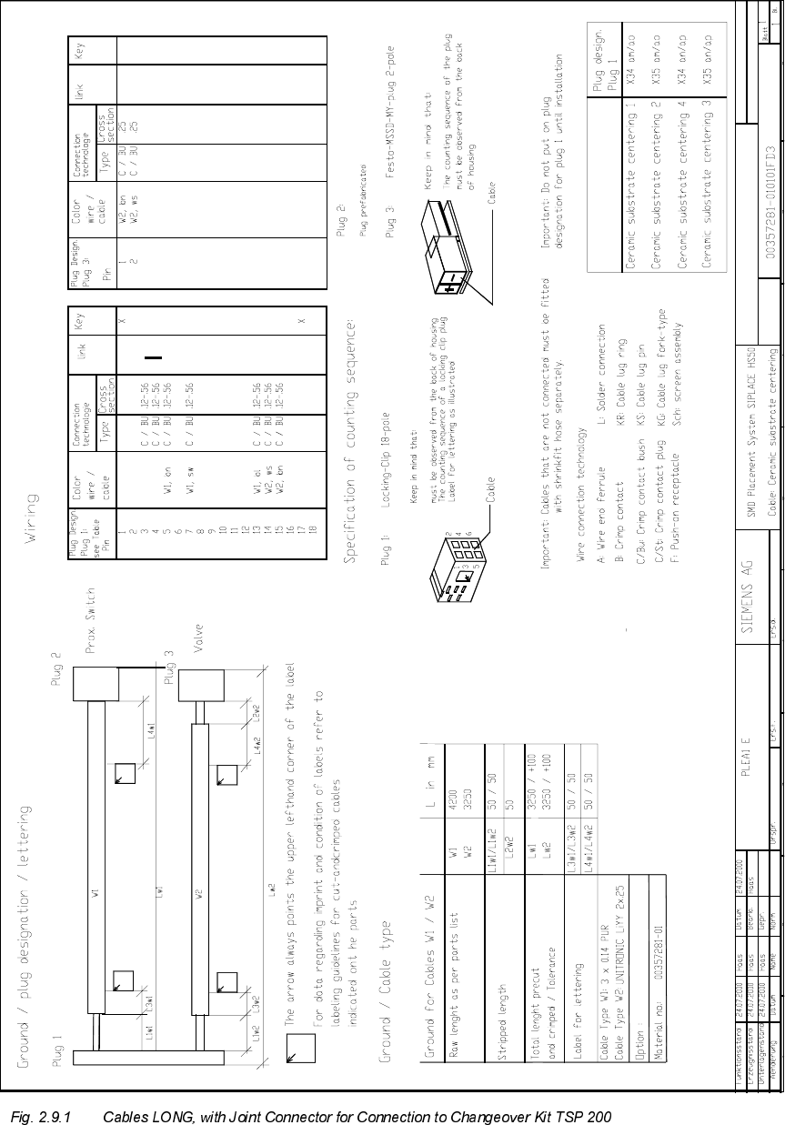
Use the LONG cables with the Item no. 00357281-01 (see Fig. 2.9.1) to connect the conversion
board ("piggyback board") of series handling TSP 200, situated in the machine frame.
The coding of the optional "mechanical ceramic substrate centering unit" is already included in the
joint plug for the connection to the conveyor control (see Fig. 2.9.5).
Therefore, no jumpers are required.
2 Retrofitting Instructions: Mechanical Ceramic Substrate Centering HS-50 SIPLACE HS-50
2.9 Appendix: Cables and Circuit Diagrams 01/01 Issue
110
SIPLACE HS-50 2 Retrofitting Instructions: Mechanical Ceramic Substrate Centering HS-50
01/01 Issue 2.9 Appendix: Cables and Circuit Diagrams
111