00192299-02.pdf - 第64页
1 Nachrüstanleitung: Mechanische Keramiksub strat-Zentrierung HS-50 SIPLACE HS-50 1.9 Anhang: Kabel und Schaltpläne Ausgabe 01/01 64 q
SIPLACE HS-50 1 Nachrüstanleitung: Mechanische Keramiksubstrat-Zentrierung HS-50
Ausgabe 01/01 1.9 Anhang: Kabel und Schaltpläne
63
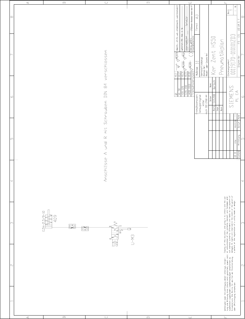
Abb. 1.9.6 Pneumatikplan: Anschluß des Magnetventils für Keramiksubstrat-Zentrierung
1 Nachrüstanleitung: Mechanische Keramiksubstrat-Zentrierung HS-50 SIPLACE HS-50
1.9 Anhang: Kabel und Schaltpläne Ausgabe 01/01
64
q
SIPLACE HS-50 2 Retrofitting Instructions: Mechanical Ceramic Substrate Centering HS-50
01/01 Issue 2.1 Overview
65
5HWURILWWLQJ,QVWUXFWLRQV 0HFKDQLFDO
&HUDPLF6XEVWUDWH&HQWHULQJ+6
2Y HUY LHZ
These instructions describe how to retrofit the optional "mechanical ceramic substrate centering
unit HS-50". Only the Siemens SMD service engineer is permitted to perform retrofitting.
– Note the following prior to the retrofitting:
– The optional "mechanical ceramic substrate centering unit of the HS-50" is always installed
in both of the conveyor’s processing areas. In the case of a dual conveyor, it is generally
also installed in both PCB conveyors.
The retrofit kit for the ceramic substrate centering unit HS-50 contains
RQO\WKHSDUWVIRU
RQHRIWKHSURFHVVLQJDUHDV
of the HS-50!
– If older HS-50 machines are involved, the 2 fastening and centering holes used to install
the mechanical substrate centering unit may not have been made in the plate of the lifting
table. This must be clarified with the customer prior to the retrofitting so that the proper num-
ber of
H[FKDQJHWDEOHSODWHV
(with holes) are taken along and the time required for retro-
fitting can be scheduled.
– If the conveyor control TSP 100 has been installed on the HS-50 placement machine, it is
upgraded to the new status of the TSP 200 at the same time that the mechanical ceramic
substrate centering unit is retrofitted.
&KDQJHRYHU KROGLQJ
for TSP 200 is used for this pur-
pose (see Section 2.3, "Requirements").
The time expended for this must be included in calculation when planning the retrofitting.
– Insofar the electrical connection ist concerned, different situations exist for the retrofitting of
mechanical ceramic substrate centering unit
as described in detail in Section 2.5.11 and
Section 2.5.12:
– Connection to the conversion board ("piggyback board") of the conveyor control
"changeover handling of TSP 200" in the machine frame.
– Connection to the conversion board (in the PCB conveyor area) of the conveyor control "se-
ries handling of TSP 200".
– The solenoid valve (for each processing area) is installed in the longitudinal cable pit on the
fixed conveyor side. The pneumatic hose of the relevant ceramic substrate centering unit is
connected via the Y-hose connection in the compressed air branch of the stopper (5.6 bar).