00192299-02.pdf - 第66页
2 Retrofitting Instructions: Mechanical Ceramic Substrate Centering HS -50 SIPLACE HS -50 2.1 Overview 01/01 Issue 66 – The conveyo r assemb lies ar e conv erted for use o f the mec hanical cerami c substr ate cente ring…
SIPLACE HS-50 2 Retrofitting Instructions: Mechanical Ceramic Substrate Centering HS-50
01/01 Issue 2.1 Overview
65
5HWURILWWLQJ,QVWUXFWLRQV 0HFKDQLFDO
&HUDPLF6XEVWUDWH&HQWHULQJ+6
2Y HUY LHZ
These instructions describe how to retrofit the optional "mechanical ceramic substrate centering
unit HS-50". Only the Siemens SMD service engineer is permitted to perform retrofitting.
– Note the following prior to the retrofitting:
– The optional "mechanical ceramic substrate centering unit of the HS-50" is always installed
in both of the conveyor’s processing areas. In the case of a dual conveyor, it is generally
also installed in both PCB conveyors.
The retrofit kit for the ceramic substrate centering unit HS-50 contains
RQO\WKHSDUWVIRU
RQHRIWKHSURFHVVLQJDUHDV
of the HS-50!
– If older HS-50 machines are involved, the 2 fastening and centering holes used to install
the mechanical substrate centering unit may not have been made in the plate of the lifting
table. This must be clarified with the customer prior to the retrofitting so that the proper num-
ber of
H[FKDQJHWDEOHSODWHV
(with holes) are taken along and the time required for retro-
fitting can be scheduled.
– If the conveyor control TSP 100 has been installed on the HS-50 placement machine, it is
upgraded to the new status of the TSP 200 at the same time that the mechanical ceramic
substrate centering unit is retrofitted.
&KDQJHRYHU KROGLQJ
for TSP 200 is used for this pur-
pose (see Section 2.3, "Requirements").
The time expended for this must be included in calculation when planning the retrofitting.
– Insofar the electrical connection ist concerned, different situations exist for the retrofitting of
mechanical ceramic substrate centering unit
as described in detail in Section 2.5.11 and
Section 2.5.12:
– Connection to the conversion board ("piggyback board") of the conveyor control
"changeover handling of TSP 200" in the machine frame.
– Connection to the conversion board (in the PCB conveyor area) of the conveyor control "se-
ries handling of TSP 200".
– The solenoid valve (for each processing area) is installed in the longitudinal cable pit on the
fixed conveyor side. The pneumatic hose of the relevant ceramic substrate centering unit is
connected via the Y-hose connection in the compressed air branch of the stopper (5.6 bar).
2 Retrofitting Instructions: Mechanical Ceramic Substrate Centering HS-50 SIPLACE HS-50
2.1 Overview 01/01 Issue
66
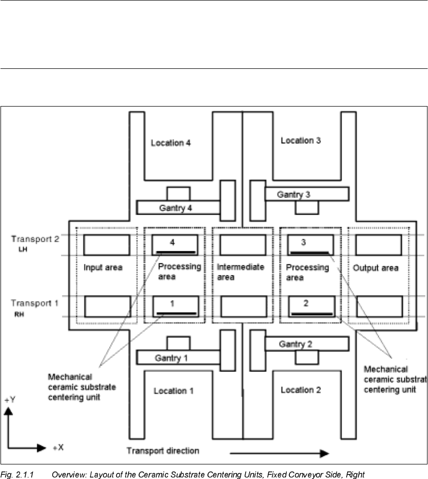
– The conveyor assemblies are converted for use of the mechanical ceramic substrate centering
unit (X-centering unit) by installing the holddowns from the retrofit kits.
– The appropriate stop rail and the appropriate stop unit (kit 1, 2 or 3) are mounted on the X-
centering unit to adapt it to the substrate size to be processed: 50 mm to 140 mm. These parts
are available, preassembled, in the retrofit kit (see Section 2.4 and Section 2.5.9).
NOTE:
On request, it is possible to perform a retrofit kit for the "mechanical ceramic substrate centering
unit HS-50" for machines HS-50 with optinal "PCB conveyor, left".
This retrofitting is not described here but can be executed in a like manner.

SIPLACE HS-50 2 Retrofitting Instructions: Mechanical Ceramic Substrate Centering HS-50
01/01 Issue 2.2 Safety Instructions
67
6DIHW\,QVWUXFWLRQV
DANGER
Only Siemens service engineers are permitted to perform the retrofitting of the "Mechanical ce-
ramic substrate centering HS-50".
Comply with the higher ranking "Safety Instructions" in Chapter "Operational Safety" in the User
Manual and Service Manual.
The machine SIPLACE HS-50 is powered by
219/380 V +/- 5% or
230/400 V +/- 5% or
239/415 V +/- 5% or
117/204 V +/- 5% or
133/230 V +/- 5%,
50/60 Hz line voltage.
Portions of the system are therefore conducting dangerous electricity, inside the machine even
while the master switch is turned off.
After you have properly carried out the shut-down of the Windows operating system NT:
BEFORE all work the machine must be turned OFF at the main switch and isolated from the
mains. In addition, the compressed air supply must be turned off at the main valve of the com-
pressed air unit in the machine base and the compressed air lines must be bled by actuating the
needle valve at the compressed air unit (particularly due to the risk of injury - posed by residual
air - at the pneumatic cutter and because of the work required in the compressed air branch).
Obey the applicable accident prevention regulations, DIN standards and special safety codes of
your country at all times. DIN EN 60204 must be adhered to during all work inside the machine
base.
Follow the instructions regarding residual voltages in Chapter "Operational Safety"
Comply with regulations on ESDs (see Chapter "Operational Safety"), e.g., when working on the
conversion PCB for the PCB conveyor control.
During the work of retrofitting secure the machine conscientiously against other personnel and
prevent it from being turned back on without authorization, as described in the User Manual in the
chapter "Locking the Machine...".
There is additional, higher risk of accident when working with the SITEST program.
The SIPLACE program is only to be started by personnel who are authorized to do so.
For the work with the SITEST program the component changeover table must be moved in and
correctly connected.