00192299-02.pdf - 第73页
SIPLACE HS-50 2 Retrofitting Instructions: Mechanical Ceramic Subs trate Centering HS-50 01/01 Issue 2.5 Sequence of Retrofitting 73 'HLQVW DOOLQ JWKH /LI WLQJ 7 DEO H3ODW HV The followin g work is to be …

2 Retrofitting Instructions: Mechanical Ceramic Substrate Centering HS-50 SIPLACE HS-50
2.5 Sequence of Retrofitting 01/01 Issue
72
6HTXHQFHRI5HWURILWWLQJ
Perform all the work in the specified order.
3UHSD UDWRU\6WHS
DANGER
Strictly adhere to the instructions in the DANGER text in Section 2.2 !
When a dual conveyor is involved, there is a risk of fingers or hands being pinched, crushed be-
tween the fixed side of conveyor 1 and the movable side of conveyor 2 when the conveyors are
travelling at maximum width.
It is not necessary to undock the movable component changeover tables to perform the retrofit-
ting. If you undock nevertheless, please note:
The X-gantry must always be moved / pushed out of the area of the component changeover table
before disconnecting the component changeover table.
Otherwise there will be a risk that the placement head may crash!!
High risk of injury exists from the blades and the tape deflector of the cutter, even when the ma-
chine has been turned off.
Never reach into the pneumatic cutter from below or into the empty-tape duct from above, not
even to resolve a problem (e.g., when tape is jammed before the component changeover table is
deinstalled).
Å Move the conveyor to maximum width so that you will be able to remove the lifting table plates
during a subsequent step.
If a dual conveyor is installed, move the conveyor 1 and 2 to maximum width.
Å The plates of the lifting tables have to be/remain lowered so that the springs of the holddowns
are not under tension during the following removal of the holddowns.
Å It is not necessary to undock the movable component changeover tables.
If you do this nevertheless, please heed the above DANGER text.
Å Turn the machine OFF, disconnect the machine from the mains and turn off the flow of com-
pressed air at the compressed air unit (see DANGER text in Section 2.2).

SIPLACE HS-50 2 Retrofitting Instructions: Mechanical Ceramic Substrate Centering HS-50
01/01 Issue 2.5 Sequence of Retrofitting
73
'HLQVWDOOLQJWKH/LIWLQJ7DEOH3ODWHV
The following work is to be performed to install the holddowns from the retrofit kit and, if necessary,
to exchange the plate of the lifting table.
The PCB conveyor is already set to maximum width.
Å Move the X-gantry / X-gantries into the area outside the PCB conveyor.
Å Undo the M3 setscrew on the ball bearing of the rocking lever, doing so on the fixed and mov-
able sides of the conveyor and in BOTH of the conveyor’s processing areas (see Fig. 2.5.2 ->
2 to 5).
Å Being careful not to lose the relevant setscrew and the spacer disk, remove the ball bearing
and, under it, the spacer disk of the relevant rocker lever.
CAUTION
When the plates of the lifting tables are picked up, there is a slight risk of fingers or hands being
pinched, crushed, e.g., between the outer edges of the lifting table plate and the mechanical con-
veyor assemblies.
Å Holding the lifting table plates with both hands, lift them out one after the other.
Å Make certain the lifting table is not tilted while being lifted.
Å Place the lifting table plate upside down on a clean, flat surface.
([FKDQJLQJWKH/LIWLQJ7DEOH3ODWHV
This work is only necessary if there are as yet NO fastening holes for the option in the lifting table
plates that were removed.
CAUTION
A great deal of force must be applied to undo the screws as described below because the screws
have been secured with Loctite no. 243.
Handle the guide pillars carefully: Make certain that they do not rolling away, being dropped or
damaged after disassembly otherwise.
Å Undo the 2 special socket hex head cap screws (size 10), used to fasten the lifting table plates
to the pillars.
2 Retrofitting Instructions: Mechanical Ceramic Substrate Centering HS-50 SIPLACE HS-50
2.5 Sequence of Retrofitting 01/01 Issue
74
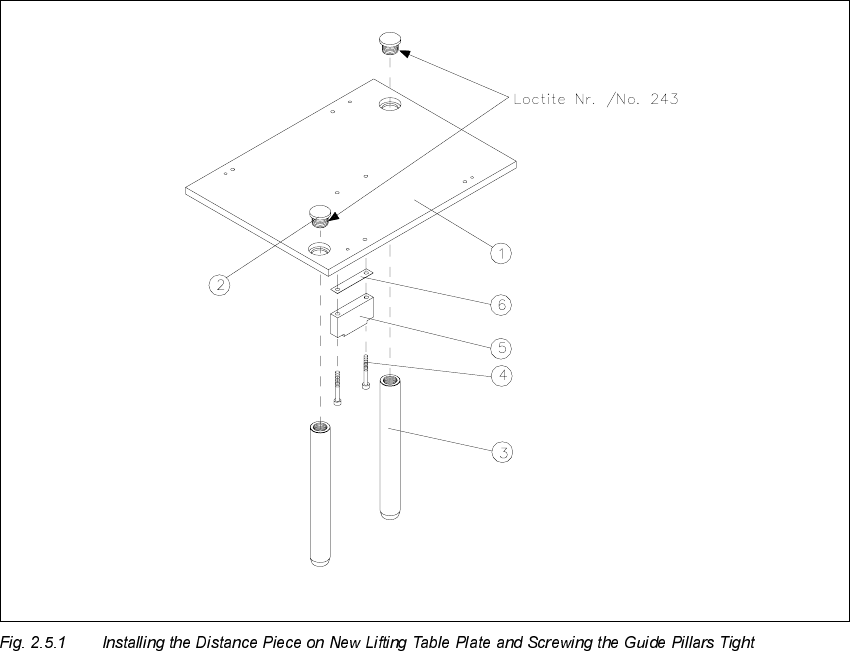
Å Remove the distance piece on the bottom of the relevant lifting table plate (2 socket hex head
cap screws M4 for each). During this process, remove the accompanying spacer plate (see
Fig. 2.5.1).
Å Install the distance piece including spacer plate on the bottom of the new lifting table plate (Item
no. see Section 2.4.2).
The 2 countersunk holes in the lifting table plate must point upward. The relief milling on the
distance piece must point upward so that the screw heads do not protrude.
.H\
1. Lifting table plate with fastening holes for mechanical ceramic substrate centering unit
2. 2 special screws secured with Loctite no. 243
(Locking screw M16 x 1.5 DIN 908, Item no. 00302081-01)
(requires a size 10 Allen wrench)
3. Guide pillars
4. 2 socket hex head cap screws M 4 x 16
5. Spacer plate
6. Distance piece, lifting table HS-50