00192299-02.pdf - 第74页
2 Retrofitting Instructions: Mechanical Ceramic Substrate Centering HS -50 SIPLACE HS -50 2.5 Sequence of Retrofitt ing 01/01 Issue 74 Å Remo ve the distance pi ece on the bottom of the relev ant lifting tab le plate (2 …

SIPLACE HS-50 2 Retrofitting Instructions: Mechanical Ceramic Substrate Centering HS-50
01/01 Issue 2.5 Sequence of Retrofitting
73
'HLQVWDOOLQJWKH/LIWLQJ7DEOH3ODWHV
The following work is to be performed to install the holddowns from the retrofit kit and, if necessary,
to exchange the plate of the lifting table.
The PCB conveyor is already set to maximum width.
Å Move the X-gantry / X-gantries into the area outside the PCB conveyor.
Å Undo the M3 setscrew on the ball bearing of the rocking lever, doing so on the fixed and mov-
able sides of the conveyor and in BOTH of the conveyor’s processing areas (see Fig. 2.5.2 ->
2 to 5).
Å Being careful not to lose the relevant setscrew and the spacer disk, remove the ball bearing
and, under it, the spacer disk of the relevant rocker lever.
CAUTION
When the plates of the lifting tables are picked up, there is a slight risk of fingers or hands being
pinched, crushed, e.g., between the outer edges of the lifting table plate and the mechanical con-
veyor assemblies.
Å Holding the lifting table plates with both hands, lift them out one after the other.
Å Make certain the lifting table is not tilted while being lifted.
Å Place the lifting table plate upside down on a clean, flat surface.
([FKDQJLQJWKH/LIWLQJ7DEOH3ODWHV
This work is only necessary if there are as yet NO fastening holes for the option in the lifting table
plates that were removed.
CAUTION
A great deal of force must be applied to undo the screws as described below because the screws
have been secured with Loctite no. 243.
Handle the guide pillars carefully: Make certain that they do not rolling away, being dropped or
damaged after disassembly otherwise.
Å Undo the 2 special socket hex head cap screws (size 10), used to fasten the lifting table plates
to the pillars.
2 Retrofitting Instructions: Mechanical Ceramic Substrate Centering HS-50 SIPLACE HS-50
2.5 Sequence of Retrofitting 01/01 Issue
74
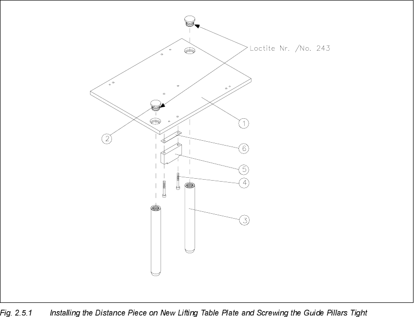
Å Remove the distance piece on the bottom of the relevant lifting table plate (2 socket hex head
cap screws M4 for each). During this process, remove the accompanying spacer plate (see
Fig. 2.5.1).
Å Install the distance piece including spacer plate on the bottom of the new lifting table plate (Item
no. see Section 2.4.2).
The 2 countersunk holes in the lifting table plate must point upward. The relief milling on the
distance piece must point upward so that the screw heads do not protrude.
.H\
1. Lifting table plate with fastening holes for mechanical ceramic substrate centering unit
2. 2 special screws secured with Loctite no. 243
(Locking screw M16 x 1.5 DIN 908, Item no. 00302081-01)
(requires a size 10 Allen wrench)
3. Guide pillars
4. 2 socket hex head cap screws M 4 x 16
5. Spacer plate
6. Distance piece, lifting table HS-50
SIPLACE HS-50 2 Retrofitting Instructions: Mechanical Ceramic Substrate Centering HS-50
01/01 Issue 2.5 Sequence of Retrofitting
75
Å Clean the Loctite residues from the threads of the 2 special screws for each table.
Å Place Loctite no. 243 (Item no. see Section 2.4.3) on the thread and bolt the guide pillars to
the lifting table plates.
Å Make certain that the longitudinal axis of the guide pillars is at right angles to the bottom of the
lifting table plate:
Å Place the lifting table plate upside down on the clean, flat surface of a table.
The guide pillars must be pointing up.
If necessary, use parallel clamp to fasten the lifting table plate to the table.
Å Place the long arm (L = approx. 160 mm) of the metal square against the guide pillar and
in the next step of work place the metal square with offset 90 degrees on the guide pillar.
If there is a deviation / gap, carefully align the pillar with the plastic hammer.
Å Do this for all 4 guide pillars of all of the modified lifting table plates.
Å Do NOT place the lifting table plates in the conveyor yet because the conveyor assemblies
have to be converted for the substrate conveyor first, as described below.