00192299-02.pdf - 第76页
2 Retrofitting Instructions: Mechanical Ceramic Substrate Centering HS -50 SIPLACE HS -50 2.5 Sequence of Retrofitt ing 01/01 Issue 76 'HLQVWDOOLQJ([LVWLQJ+ROGGRZ QV
SIPLACE HS-50 2 Retrofitting Instructions: Mechanical Ceramic Substrate Centering HS-50
01/01 Issue 2.5 Sequence of Retrofitting
75
Å Clean the Loctite residues from the threads of the 2 special screws for each table.
Å Place Loctite no. 243 (Item no. see Section 2.4.3) on the thread and bolt the guide pillars to
the lifting table plates.
Å Make certain that the longitudinal axis of the guide pillars is at right angles to the bottom of the
lifting table plate:
Å Place the lifting table plate upside down on the clean, flat surface of a table.
The guide pillars must be pointing up.
If necessary, use parallel clamp to fasten the lifting table plate to the table.
Å Place the long arm (L = approx. 160 mm) of the metal square against the guide pillar and
in the next step of work place the metal square with offset 90 degrees on the guide pillar.
If there is a deviation / gap, carefully align the pillar with the plastic hammer.
Å Do this for all 4 guide pillars of all of the modified lifting table plates.
Å Do NOT place the lifting table plates in the conveyor yet because the conveyor assemblies
have to be converted for the substrate conveyor first, as described below.
2 Retrofitting Instructions: Mechanical Ceramic Substrate Centering HS-50 SIPLACE HS-50
2.5 Sequence of Retrofitting 01/01 Issue
76
'HLQVWDOOLQJ([LVWLQJ+ROGGRZQV
SIPLACE HS-50 2 Retrofitting Instructions: Mechanical Ceramic Substrate Centering HS-50
01/01 Issue 2.5 Sequence of Retrofitting
77
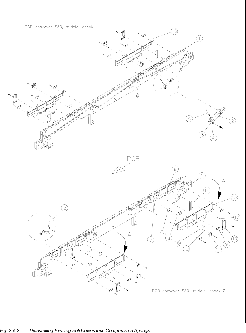
.H\WR)LJ
A) Direction of movement for deinstalling the holddowns (left, right)
1. Conveyor assembly (fixed or movable side)
2. Rocker lever, fixed or movable side: DO NOT DEINSTALL
3. Setscrew M3 x 5
4. Ball bearing and spacer disk (remove for deinstallation of the lifting table plate)
5. Compression spring on the rocker lever
6. PCB guide rail (all remained installed)
7. Compression spring for holddown
8. Retaining bracket (support)
9. DU strip (3 units)
10. Cassette 1 or 2, guide for holddown
11. Cassette 3, guide for holddown
12.Adjusting shim 3 x 4.5 x 0.1 mm
13.Sliding strip 2 for holddown
14. Sliding strip for holddown
15. Holddown (to be deinstalled)
16.Fasteners for support: 2 slotted screws M4 x 6
Carry out the following steps on the fixed and movable conveyor side for each of the two pro-
cessing areas of the conveyor to be retrofitted (1 / 2):
Å Remove the 3 DU strips (see Fig. 2.5.2 -> 9) and the two guides for the guides for the hold-
downs (see Fig. 2.5.2 -> 10 and 11) on the exterior of the conveyor.
To do so, undo and remove the M3 cross-slotted and hexagonal socket head cap screws.
Being careful not to lose the adjusting shims (see Fig. 2.5.2 -> 12).
Å During the subsequent removal of the holddowns make certain that each of the 2 compression
springs (see Fig. 2.5.2 -> 7, 8) are not lost:
Å For dual conveyor: Now reduce the conveyor width somewhat by carefully moving the
toothed belt in the appropriate direction. Exert just a little force during this process and only
in the direction in which the toothed belt moves.
Å Fold the holddown device to the outside (direction of movement: see Fig. 2.5.2 -> A) and
take it off. While doing so, remove the compression spring from the retaining bracket (sup-
port): see Fig. 2.5.2 -> 7 and 8.