00192299-02.pdf - 第79页
SIPLACE HS-50 2 Retrofitting Instructions: Mechanical Ceramic Subs trate Centering HS-50 01/01 Issue 2.5 Sequence of Retrofitting 79 NOTE: The PCB hol ddown b rackets from the retrofi t kit are no t install ed while th e…
2 Retrofitting Instructions: Mechanical Ceramic Substrate Centering HS-50 SIPLACE HS-50
2.5 Sequence of Retrofitting 01/01 Issue
78
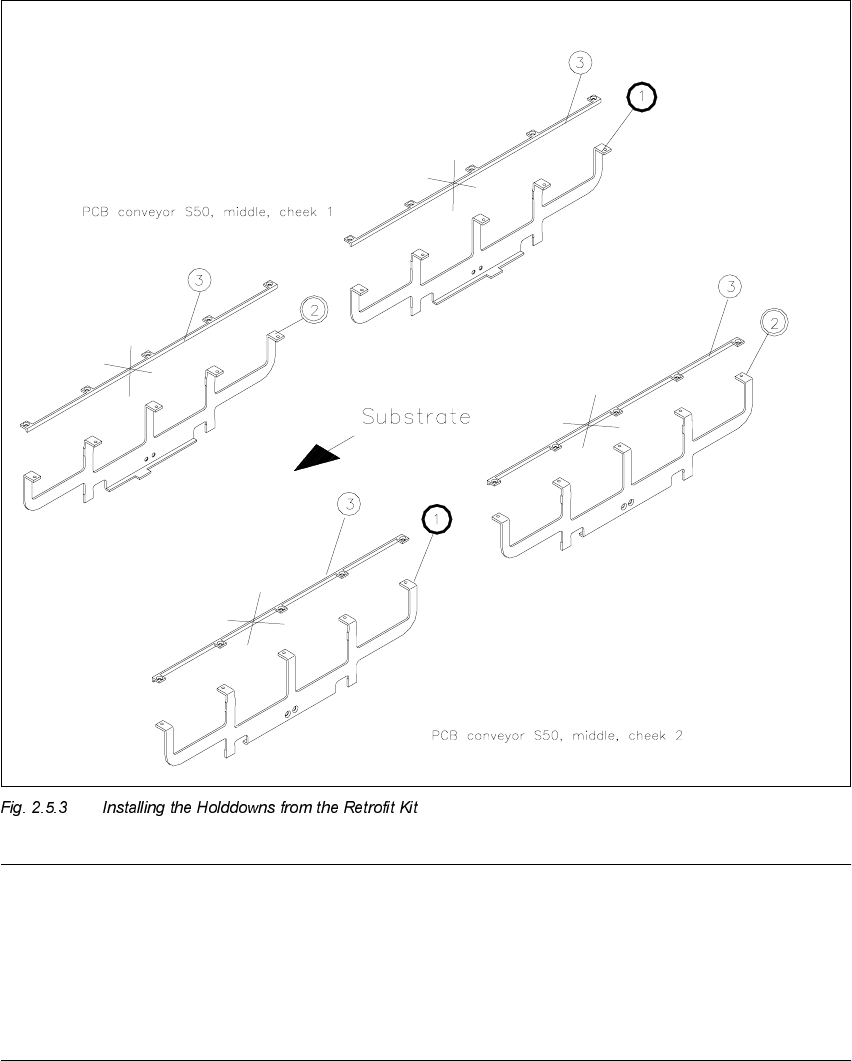
,QVWDOOLQJWKH+ROGGRZQVIURPWKH5HWURILW.LW
Å During this process, exchange the compression spring of the pertinent holddown (see Fig.
2.5.2 -> 7), if the spring is shorter than 32 mm when not loaded -> Item no. of compression
spring: see Section 2.4.2.
Å Install the appropriate holddown from the retrofit kit incl. the (new, if necessary) compression
spring with retaining bracket (support) on the conveyor assembly and install it in the reverse
order to the steps as described in Section 2.5.4 for deinstallation.
.H\WR)LJ
1. Holddown 1
2. Holddown 2
3. PCB holddown bracket on fixed and movable side:
Only for reinstallation on the PCB centering unit
(fasteners: 5 countersunk screws each M3 x 6).
SIPLACE HS-50 2 Retrofitting Instructions: Mechanical Ceramic Substrate Centering HS-50
01/01 Issue 2.5 Sequence of Retrofitting
79
NOTE:
The PCB holddown brackets from the retrofit kit are not installed while the mechanical substrate
centering unit is being worked on.
Store the PCB holddown brackets as well as the remaining stop units and stop rails in such a man-
ner that they are available for a later reinstallation (see Section 2.8) or adapting of the substrate
size (see Section 2.5.9).

2 Retrofitting Instructions: Mechanical Ceramic Substrate Centering HS-50 SIPLACE HS-50
2.5 Sequence of Retrofitting 01/01 Issue
80
,QVWDOOLQJWKH/LIWLQJ7D EOH
CAUTION
During the subsequent installation of the lifting table plate there is a slight risk of fingers and hands
being pinched, crushed or cut off, e.g., between the outer edges of the lifting table plate and the
conveyor assemblies.
Å If a dual conveyor is installed, restore the conveyor to maximum width by moving the toothed
belt of the conveyor width adjustment assy to maximum width.
During this process, exert just a little force and do so only in the direction in which the toothed
belt is moving.
Å Make certain that the transmission lever on the pertinent lifting table motor is folded down on
the lifting curve.
Å Holding the lifting table with both hands, place it into the guiding tubes with the guide pillars
vertical.
Å Let the lifting table plate slide down slowly.
Å Check whether the lifting table plate is completely seated on the lifting curve.
Å Install the pertinent ball bearing on each rocking lever (see Fig. 2.5.2 -> 2).
While doing so, put the spacer disk back in.