00192299-02.pdf - 第83页
SIPLACE HS-50 2 Retrofitting Instructions: Mechanical Ceramic Subs trate Centering HS-50 01/01 Issue 2.5 Sequence of Retrofitting 83 Å On th e X-slide unit loos en the stop rail a ssembl y fastene rs (2 soc ket hex head …

2 Retrofitting Instructions: Mechanical Ceramic Substrate Centering HS-50 SIPLACE HS-50
2.5 Sequence of Retrofitting 01/01 Issue
82
During this process, insert the 2 socket hex head cap screws M4 x 45 from above (see Fig.
2.5.4 -> 3, 4).
Å Use them to bolt the body of the centering unit onto the lifting table.
Å Adapt the X-centering unit to the substrate size to be handled next (see Section 2.5.9).
6HWWLQJWKH2SHUDWLQJ'LVWDQFHRIWKH3UR[LPLW\6ZLWFK
Å Make certain that the operating surface of the inductive proximity switch is set 0.2 mm back
from the stop surface of the slide unit in the hole.
This precludes the possibility that the proximity switch might serve as a stop during the opening
movement and being damaged as a result.
Å If necessary, correct the position of the proximity switch (grub screw, size 1 Allen wrench).
The proximity switch has an LED for checking the switching process.
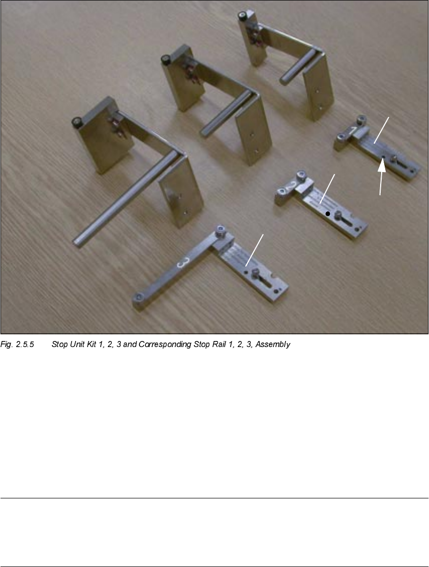
$GDSWLQJWRWKH6XEVWUDWH6L]H
To ensure the 3-point contact of the substrate for the centering unit in the X-direction, the ceramic
substrate centering unit has to be adapted to the substrate size to be processed afterwards.
To do this, install the pertinent stop rail (with 2 ball bearings) and the pertinent stop unit (with sta-
tionary roller AND distance bolt) -> Item no. see table below.
CAUTION
The distance bolt ist not to remove ! .
Designation For substrate width Item no.
Stop rail 1 assembly
with parallel pin
for 50 mm to 62 mm 00358877-01
Stop rail 2 assembly for > 62 mm to 106 mm 00358884-01
Stop rail 3 assembly for > 106 mm to 140 mm 00358885-01
Stop unit kit 1 (complete
with distance bolt)
for 50 mm to 62 mm 00358874-01
Stop unit kit 2 (complete
with distance bolt)
for > 62 mm to 106 mm 00358875-01
Stop unit kit 3 (complete
with distance bolt)
for > 106 mm to 140 mm 00358876-01
SIPLACE HS-50 2 Retrofitting Instructions: Mechanical Ceramic Substrate Centering HS-50
01/01 Issue 2.5 Sequence of Retrofitting
83
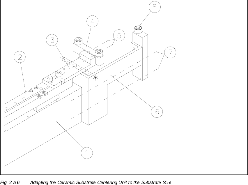
Å On the X-slide unit loosen the stop rail assembly fasteners (2 socket hex head cap screws
M 3: see Fig. 2.5.6 -> 4, 5).
Å Mount the required stop rail assembly (see table above and Fig. 2.5.5).
1. Stop unit Kit
, fixed stop
2. Stop unit Kit
, fixed stop
3. Stop unit Kit
, fixed stop
4. Stop rail
DQG
, assembly (see
PDUNVDQG
), movable stop
5. Parallel pin to limit the lift:
Must be on stop rail 1.
NOTE:
Install the stop unit kit 1 (fixed stop) and stop rail "", assembly (= movable stop) for substrates
PPWRPPZLGHWKDWDUHPRUHWKDQPPORQJ(e. g., twice as long): See table above
and Fig. 2.5.5).
2 Retrofitting Instructions: Mechanical Ceramic Substrate Centering HS-50 SIPLACE HS-50
2.5 Sequence of Retrofitting 01/01 Issue
84
Å Loosen the screws fastening the stop unit to the X-slide unit (2 socket hex head cap screws
M3: see Fig. 2.5.6 -> 6, 7).
Å Install the required stop unit, kit 1, 2 or 3 (see table above).
1. Body of the centering unit
2. X-slide unit
3. Fastening bracket for stop rail, 2 socket head cap screws M3 x 8
4. Stop rail (depending on size of substrate: see table above)
5. 2 socket hex head cap screws M3
6. Stop unit WITH distance bolt, complete (depending on size of substrate: see table above)
7. Screws to fasten the stop unit: 2 socket hex head cap screws M3
8. Stationary stop roller