00192299-02.pdf - 第84页
2 Retrofitting Instructions: Mechanical Ceramic Substrate Centering HS -50 SIPLACE HS -50 2.5 Sequence of Retrofitt ing 01/01 Issue 84 Å Loo sen the screws fa stening t he stop unit to the X-slide unit (2 s ocket he x he…
SIPLACE HS-50 2 Retrofitting Instructions: Mechanical Ceramic Substrate Centering HS-50
01/01 Issue 2.5 Sequence of Retrofitting
83
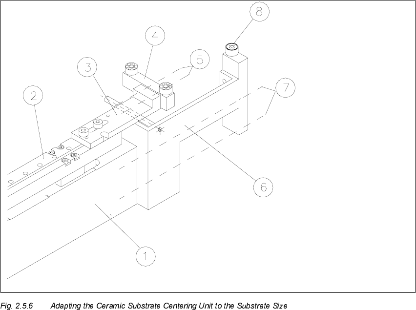
Å On the X-slide unit loosen the stop rail assembly fasteners (2 socket hex head cap screws
M 3: see Fig. 2.5.6 -> 4, 5).
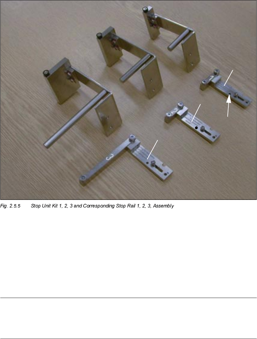
Å Mount the required stop rail assembly (see table above and Fig. 2.5.5).
1. Stop unit Kit
, fixed stop
2. Stop unit Kit
, fixed stop
3. Stop unit Kit
, fixed stop
4. Stop rail
DQG
, assembly (see
PDUNVDQG
), movable stop
5. Parallel pin to limit the lift:
Must be on stop rail 1.
NOTE:
Install the stop unit kit 1 (fixed stop) and stop rail "", assembly (= movable stop) for substrates
PPWRPPZLGHWKDWDUHPRUHWKDQPPORQJ(e. g., twice as long): See table above
and Fig. 2.5.5).
2 Retrofitting Instructions: Mechanical Ceramic Substrate Centering HS-50 SIPLACE HS-50
2.5 Sequence of Retrofitting 01/01 Issue
84
Å Loosen the screws fastening the stop unit to the X-slide unit (2 socket hex head cap screws
M3: see Fig. 2.5.6 -> 6, 7).
Å Install the required stop unit, kit 1, 2 or 3 (see table above).
1. Body of the centering unit
2. X-slide unit
3. Fastening bracket for stop rail, 2 socket head cap screws M3 x 8
4. Stop rail (depending on size of substrate: see table above)
5. 2 socket hex head cap screws M3
6. Stop unit WITH distance bolt, complete (depending on size of substrate: see table above)
7. Screws to fasten the stop unit: 2 socket hex head cap screws M3
8. Stationary stop roller
SIPLACE HS-50 2 Retrofitting Instructions: Mechanical Ceramic Substrate Centering HS-50
01/01 Issue 2.5 Sequence of Retrofitting
85
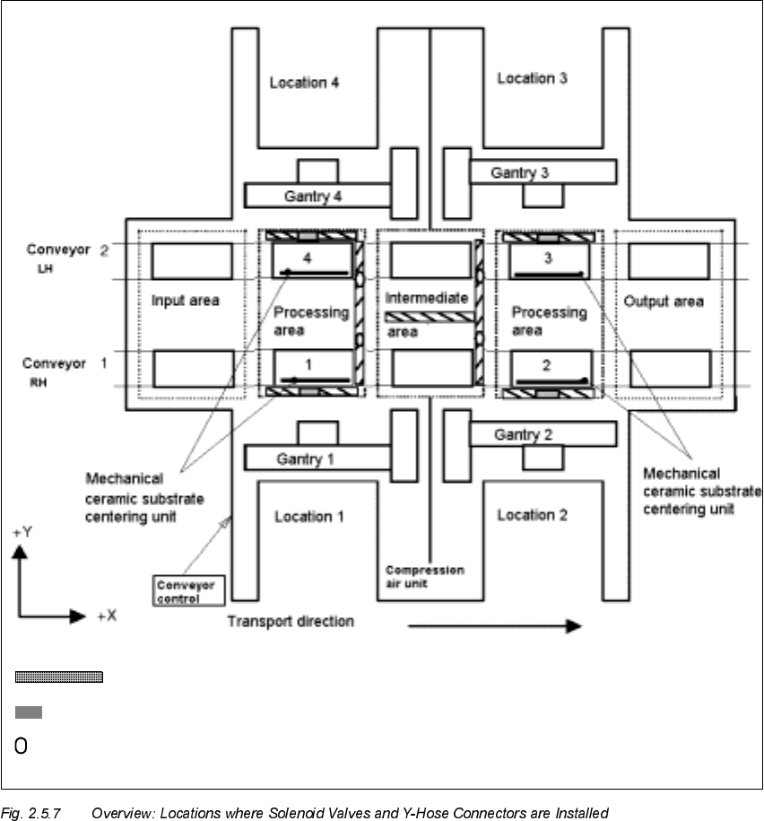
,QVWDOOLQJWKH<+RVH&RQQH FW RUDQG6ROHQRLG9D OY HV
Solenoid valve 2, 2, 3, 4
Y-hose connector in the compressed air branch of the stopper (5.6 bar)
Cable pit