00192299-02.pdf - 第85页
SIPLACE HS-50 2 Retrofitting Instructions: Mechanical Ceramic Subs trate Centering HS-50 01/01 Issue 2.5 Sequence of Retrofitting 85 ,QVWDOOLQJWKH< +RVH&RQQH FW RUDQG6ROHQRLG9 D OY HV Soleno id v…
2 Retrofitting Instructions: Mechanical Ceramic Substrate Centering HS-50 SIPLACE HS-50
2.5 Sequence of Retrofitting 01/01 Issue
84
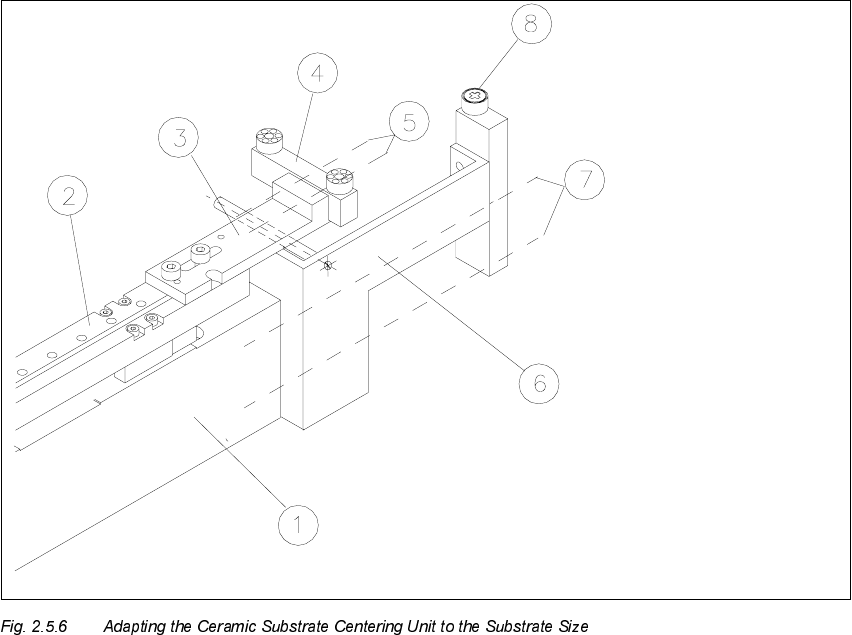
Å Loosen the screws fastening the stop unit to the X-slide unit (2 socket hex head cap screws
M3: see Fig. 2.5.6 -> 6, 7).
Å Install the required stop unit, kit 1, 2 or 3 (see table above).
1. Body of the centering unit
2. X-slide unit
3. Fastening bracket for stop rail, 2 socket head cap screws M3 x 8
4. Stop rail (depending on size of substrate: see table above)
5. 2 socket hex head cap screws M3
6. Stop unit WITH distance bolt, complete (depending on size of substrate: see table above)
7. Screws to fasten the stop unit: 2 socket hex head cap screws M3
8. Stationary stop roller
SIPLACE HS-50 2 Retrofitting Instructions: Mechanical Ceramic Substrate Centering HS-50
01/01 Issue 2.5 Sequence of Retrofitting
85
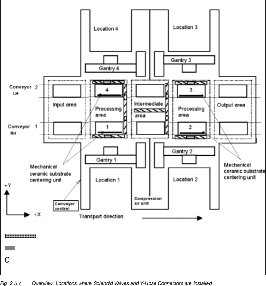
,QVWDOOLQJWKH<+RVH&RQQH FW RUDQG6ROHQRLG9D OY HV
Solenoid valve 2, 2, 3, 4
Y-hose connector in the compressed air branch of the stopper (5.6 bar)
Cable pit
2 Retrofitting Instructions: Mechanical Ceramic Substrate Centering HS-50 SIPLACE HS-50
2.5 Sequence of Retrofitting 01/01 Issue
86
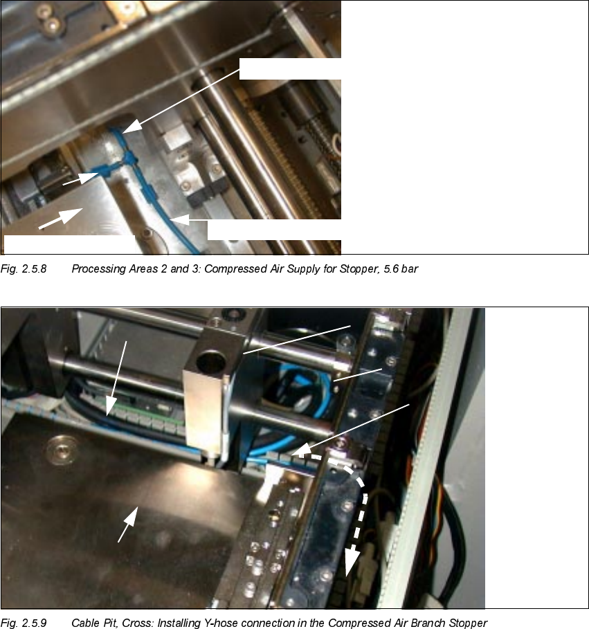
.H\
1. Y-hose connection (manufacturer = Festo) in the compressed air branch stopper 5.6 bar
2. Pneumatic hose to ceramic substrate centering unit
3. Pneumatic hose to stopper
4. Stopper
EDU
t
to stopper, conveyor 2
to stopper, conveyor 1
t
Transport
direction
7U DQVSRUWGLUHFWLRQ