00192299-02.pdf - 第86页
2 Retrofitting Instructions: Mechanical Ceramic Substrate Centering HS -50 SIPLACE HS -50 2.5 Sequence of Retrofitt ing 01/01 Issue 86 .H\ 1. Y -hos e connec tion (man ufacture r = Festo ) in the c ompresse d air bran…
SIPLACE HS-50 2 Retrofitting Instructions: Mechanical Ceramic Substrate Centering HS-50
01/01 Issue 2.5 Sequence of Retrofitting
85
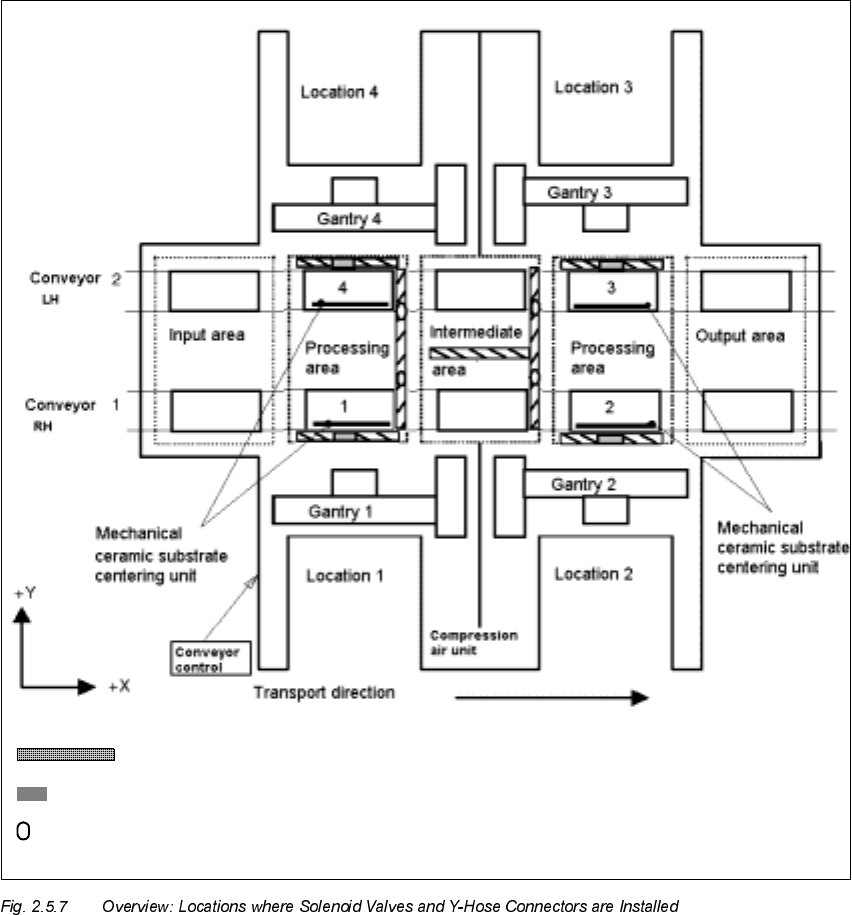
,QVWDOOLQJWKH<+RVH&RQQH FW RUDQG6ROHQRLG9D OY HV
Solenoid valve 2, 2, 3, 4
Y-hose connector in the compressed air branch of the stopper (5.6 bar)
Cable pit
2 Retrofitting Instructions: Mechanical Ceramic Substrate Centering HS-50 SIPLACE HS-50
2.5 Sequence of Retrofitting 01/01 Issue
86
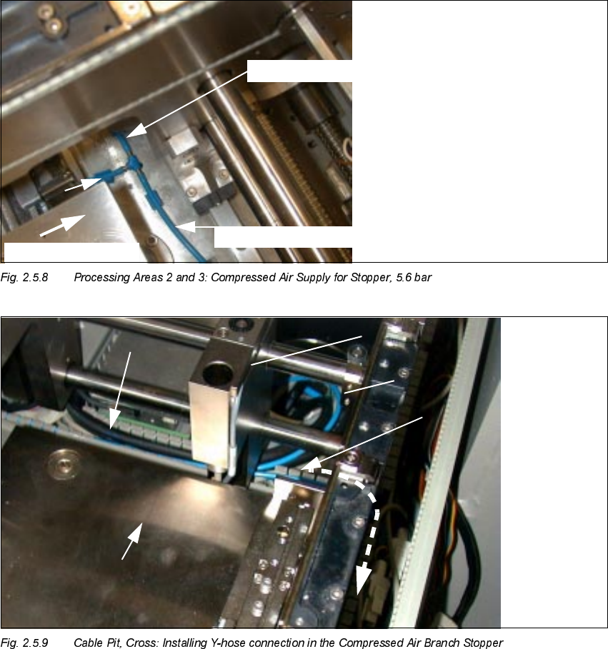
.H\
1. Y-hose connection (manufacturer = Festo) in the compressed air branch stopper 5.6 bar
2. Pneumatic hose to ceramic substrate centering unit
3. Pneumatic hose to stopper
4. Stopper
EDU
t
to stopper, conveyor 2
to stopper, conveyor 1
t
Transport
direction
7U DQVSRUWGLUHFWLRQ
SIPLACE HS-50 2 Retrofitting Instructions: Mechanical Ceramic Substrate Centering HS-50
01/01 Issue 2.5 Sequence of Retrofitting
87
Perform the following work for both processing areas of the conveyor to undergo retrofitting.
Å The compressed air is turned OFF.
Å Open the cable pit running longitudinal and crosswise to the conveyor (see Fig. 2.5.7 and Fig.
2.5.9).
Å Remove the pneumatic hose running to the pneumatic hose (compressed air branch 5.6 bar)
from the crosswise cable pit (see Fig. 2.5.9) and cut through the hose.
Å Insert the Y-hose connector (manufacturer = Festo, Item no. see Section 2.4.1):
Connect the end of the hose coming from the compressed air unit, the hose leading to the stop-
per and the pneumatic hose from the retrofit kit to the Y-hose connection.
Å Put the Y-hose connection and hoses back in the cable pit.
Å Lay the free end of the hose further into the longitudinal pit (the pit running parallel to the con-
veyor) and to the location at which the solenoid station is to be mounted (see Fig. 2.5.9 and
Fig. 2.5.10).
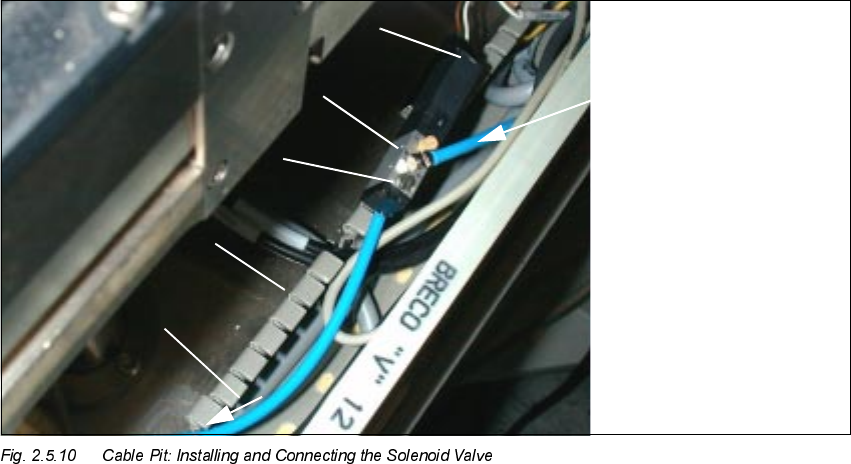
Å Put the solenoid valve into the cable pit.
.H\
1. Pneumatic hose coming from the Y-hose connector (compressed hose branch, stopper)
2. Solenoid valve (from retrofit kit)
3. Cable pit, longitudinal
4. Manual actuator
5. Plug-in connection: cable, solenoid valve
6. Pneumatic hose to the mech. ceramic substrate centering unit