00192299-02.pdf - 第87页
SIPLACE HS-50 2 Retrofitting Instructions: Mechanical Ceramic Subs trate Centering HS-50 01/01 Issue 2.5 Sequence of Retrofitting 87 Perform th e follo wing wo rk for both processi ng areas of the co nveyor to underg o r…
2 Retrofitting Instructions: Mechanical Ceramic Substrate Centering HS-50 SIPLACE HS-50
2.5 Sequence of Retrofitting 01/01 Issue
86
.H\
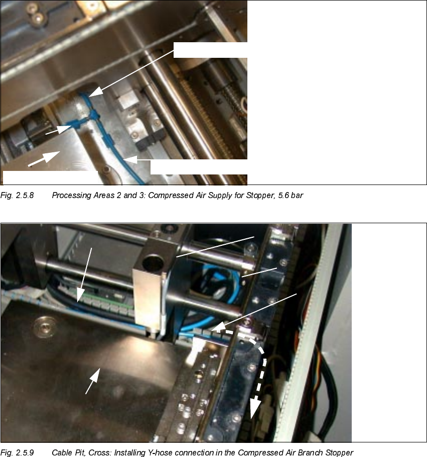
1. Y-hose connection (manufacturer = Festo) in the compressed air branch stopper 5.6 bar
2. Pneumatic hose to ceramic substrate centering unit
3. Pneumatic hose to stopper
4. Stopper
EDU
t
to stopper, conveyor 2
to stopper, conveyor 1
t
Transport
direction
7U DQVSRUWGLUHFWLRQ
SIPLACE HS-50 2 Retrofitting Instructions: Mechanical Ceramic Substrate Centering HS-50
01/01 Issue 2.5 Sequence of Retrofitting
87
Perform the following work for both processing areas of the conveyor to undergo retrofitting.
Å The compressed air is turned OFF.
Å Open the cable pit running longitudinal and crosswise to the conveyor (see Fig. 2.5.7 and Fig.
2.5.9).
Å Remove the pneumatic hose running to the pneumatic hose (compressed air branch 5.6 bar)
from the crosswise cable pit (see Fig. 2.5.9) and cut through the hose.
Å Insert the Y-hose connector (manufacturer = Festo, Item no. see Section 2.4.1):
Connect the end of the hose coming from the compressed air unit, the hose leading to the stop-
per and the pneumatic hose from the retrofit kit to the Y-hose connection.
Å Put the Y-hose connection and hoses back in the cable pit.
Å Lay the free end of the hose further into the longitudinal pit (the pit running parallel to the con-
veyor) and to the location at which the solenoid station is to be mounted (see Fig. 2.5.9 and
Fig. 2.5.10).
Å Put the solenoid valve into the cable pit.
.H\
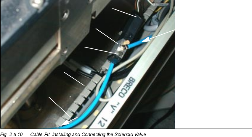
1. Pneumatic hose coming from the Y-hose connector (compressed hose branch, stopper)
2. Solenoid valve (from retrofit kit)
3. Cable pit, longitudinal
4. Manual actuator
5. Plug-in connection: cable, solenoid valve
6. Pneumatic hose to the mech. ceramic substrate centering unit
2 Retrofitting Instructions: Mechanical Ceramic Substrate Centering HS-50 SIPLACE HS-50
2.5 Sequence of Retrofitting 01/01 Issue
88
Å Cut off the excess length of hose at the solenoid valve and connect the hose end at the entry
to the solenoid valve (see Fig. 2.5.10).
Å Connect the remaining pneumatic hose to the threaded hose coupling at the exit of the sole-
noid valve (see Fig. 2.5.10 and pneumatic diagramm Fig. 2.9.6).
Å Lay this hose to the cable pit running crosswise to the to the transport direction and further to
the substrate centering unit on the fixed conveyor side (see Fig. 2.5.14).
Å Lay the cables for the proximity switch and solenoid valve as appropriate based on the version
of conveyor control available (changeover or series handling) as described in the pertinent sec-
tion below.
&KDQJHRYHU+DQGOLQJ763/D\LQJDQG&RQQHFWLQJ&DEOH
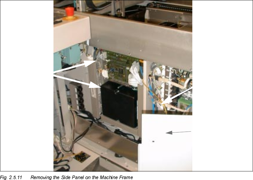
– With the installed changeover handling, the electrical connection of the mechanical ceramic
substrate centering unit HS-50 is made at the conversion board ("piggyback board") of the con-
veyor control in the machine base (see Fig. 2.5.11 and Fig. 2.5.13).
In this case, use the LONG proximity switch cable and solenoid valve cable, Item no.
00357281-0.
The coding has already been integrated into the (joint) plug for the connection to the conveyor
control.
Conveyor
control
Grounding cable
Place the side panel
on one side