00192299-02.pdf - 第89页
SIPLACE HS-50 2 Retrofitting Instructions: Mechanical Ceramic Subs trate Centering HS-50 01/01 Issue 2.5 Sequence of Retrofitting 89 Å Unplug the plug- in conn ection of the mov able com ponent ch angeover table on the m…
2 Retrofitting Instructions: Mechanical Ceramic Substrate Centering HS-50 SIPLACE HS-50
2.5 Sequence of Retrofitting 01/01 Issue
88
Å Cut off the excess length of hose at the solenoid valve and connect the hose end at the entry
to the solenoid valve (see Fig. 2.5.10).
Å Connect the remaining pneumatic hose to the threaded hose coupling at the exit of the sole-
noid valve (see Fig. 2.5.10 and pneumatic diagramm Fig. 2.9.6).
Å Lay this hose to the cable pit running crosswise to the to the transport direction and further to
the substrate centering unit on the fixed conveyor side (see Fig. 2.5.14).
Å Lay the cables for the proximity switch and solenoid valve as appropriate based on the version
of conveyor control available (changeover or series handling) as described in the pertinent sec-
tion below.
&KDQJHRYHU+DQGOLQJ763/D\LQJDQG&RQQHFWLQJ&DEOH
– With the installed changeover handling, the electrical connection of the mechanical ceramic
substrate centering unit HS-50 is made at the conversion board ("piggyback board") of the con-
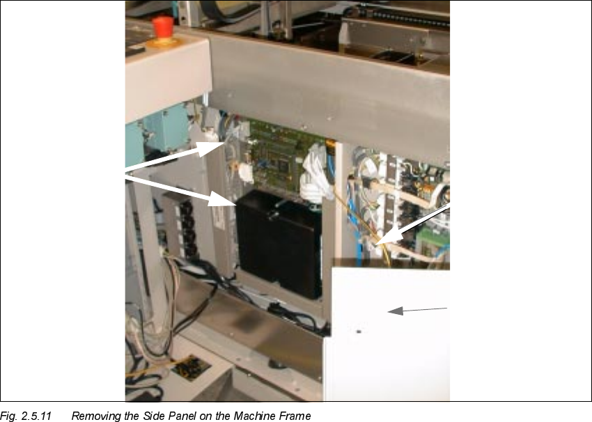
veyor control in the machine base (see Fig. 2.5.11 and Fig. 2.5.13).
In this case, use the LONG proximity switch cable and solenoid valve cable, Item no.
00357281-0.
The coding has already been integrated into the (joint) plug for the connection to the conveyor
control.
Conveyor
control
Grounding cable
Place the side panel
on one side
SIPLACE HS-50 2 Retrofitting Instructions: Mechanical Ceramic Substrate Centering HS-50
01/01 Issue 2.5 Sequence of Retrofitting
89
Å Unplug the plug-in connection of the movable component changeover table on the machine
frame.
Å Open the doors of the machine frame (see Fig. 2.5.11).
NOTE:
During the following steps, do not pull on the grounding cable that is attached to the inside of the
side panel (see Fig. 2.5.11).
Å The safety hood above the conveyor control must be open. Undo the 6 socket hex head cap
screws on the side panel (just loosen the 3 screws at the bottom!). Lift the side panel of the
machine frame up and out and place it to the side such that the conveyor control is accessible
and the grounding cable is not damaged.
Å Remove the cover over the cable pits running from the processing area to the circular cutout
(arrow).
Å Use the long cables from the retrofit kit (Item no. 00357281-01).
Use a waterproof marker to indicate the allocation to the processing area on the pertinent cable
of proximity switch and solenoid valve: In accordance with the layout plan in Fig. 2.9.1 and Fig.
2.9.3, as appropriate, mark the pertinent connector designation,

2 Retrofitting Instructions: Mechanical Ceramic Substrate Centering HS-50 SIPLACE HS-50
2.5 Sequence of Retrofitting 01/01 Issue
90
- X34 am/ap or am/ao and X35 am/ap or am/ao and, if needed,
- C1 /C2 (for conveyor 1 / conveyor 2),
on the label of the pertinent connector.
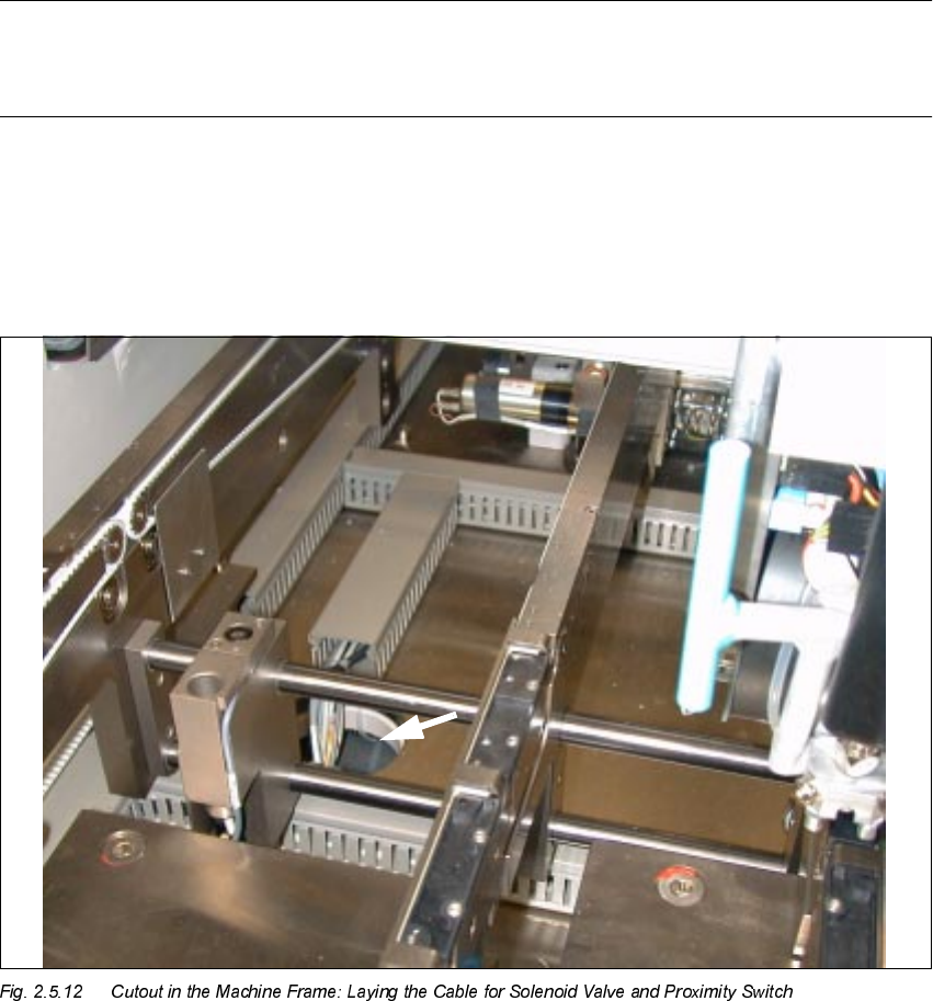
Å Starting from the pertinent X-centering unit and from the solenoid valve lay the long cables to
the cable pit leading to the circular cutout (see Fig. 2.5.12) -> downward in the cutout -> con-
tinuing through the inside of the machine frame to the rectangular cutout at the bottom left,
alongside the conveyor control (see Fig. 2.5.11) and to the outside to the conveyor control.
Å Remove the covers over the cable pits and the conveyor control for conveyor 1 / 2 in the ma-
chine frame (changeover handling: see Fig. 2.5.13).
Å Lay the cables for conveyor 1 or 2 to the pertinent conversion board ("piggyback board") of the
TSP 200 in the machine frame.
NOTE:
The conversion board ("piggyback board") of changeover handling unit TSP 200 in the machine
frame (see Fig. 2.9.5) and the conversion board of the series handling unit TSP 200 in the PCB
conveyor are identical.