00192299-02.pdf - 第92页
2 Retrofitting Instructions: Mechanical Ceramic Substrate Centering HS -50 SIPLACE HS -50 2.5 Sequence of Retrofitt ing 01/01 Issue 92 6HULHV +DQGOLQJ763/D\ LQJDQG&RQQ HF WLQJ&DEOH V When ser ie…
SIPLACE HS-50 2 Retrofitting Instructions: Mechanical Ceramic Substrate Centering HS-50
01/01 Issue 2.5 Sequence of Retrofitting
91
NOTE:
In the case of a single conveyor, only the conveyor control "Conveyor 1" at the bottom is installed.
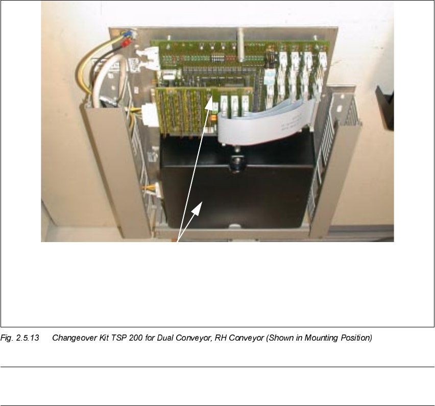
Å Lay the long cable for the solenoid valve and proximity switch for all other retrofitted X-center-
ing units, from the pertinent processing area to the corresponding "piggyback board" (see Fig.
2.5.13), as described above.
Å Make the plug-in connections of the cables for the solenoid valve and proximity switch on the
"piggyback board" with the correct allocation (see Fig. 2.9.1 and/or Fig. 2.9.3).
Å Resume the work with Section 2.5.13.
817(1
&RQYH\RU
&RQYH\R U
Conversion board PCB conveyor HS-50
PCB 893
("Piggyback board")
TOP
2 Retrofitting Instructions: Mechanical Ceramic Substrate Centering HS-50 SIPLACE HS-50
2.5 Sequence of Retrofitting 01/01 Issue
92
6HULHV +DQGOLQJ763/D\LQJDQG&RQQ HF WLQJ&DEOH V
When series handling of conveyor control is available, the optional ceramic substrate centering
unit is connected directly to the conversion board in the pertinent conveyor area. The SHORT ca-
bles (Item no. 00356 617-01) in the retrofit kit of the ceramic substrate centering unit are used for
this purpose.
The conversion board is accessible when the lifting table plate is installed.
The cables running from the "conversion board conveyor" to the conveyor control in the machine
frame were already laid and connected at the factory.
Å Use the SHORT cables from the retrofit kit ((Item no. 00356 617-01).
Use a waterproof marker to indicate the allocation to the processing area on the pertinent cable
of proximity switch and solenoid valve: In accordance with the layout plan in Fig. 2.9.2 and Fig.
2.9.4, as appropriate, mark the pertinent connector designation,
- X34 am/ap or am/ao and X35 am/ap or am/ao and, if needed,
- C1 /C2 (for conveyor 1 / conveyor 2),
on the label of the pertinent connector.
Å In the PCB processing area, remove the cover from the conversion board and from the corre-
sponding cable pits.
Å Lay the cables from the conversion board in conveyor 1 or 2 further in the cable pit alongside
the fixed conveyor side -> further to the allocated solenoid valve or the centering unit.
Å Make the plug-in connections of the pertinent solenoid-valve and proximity switch cable on the
conversion board in the PCB in the PCB conveyor area (see Fig. 2.9.4 or Fig. 2.9.5).
Å Continue the work with Section 2.5.13.
SIPLACE HS-50 2 Retrofitting Instructions: Mechanical Ceramic Substrate Centering HS-50
01/01 Issue 2.5 Sequence of Retrofitting
93
0DNLQJ&RQQHFW LRQVLQWKH3URF HVVLQJ$UH D
Å Make the plug-in connection on the allocated solenoid valve.
Å Starting from the solenoid valve, run the pneumatic hose -> further in the crosswise cable pit
to the ceramic substrate centering unit (processing areas 2 and 3).
DANGER
Do not perform the cleaning work with alcohol near an open flame.
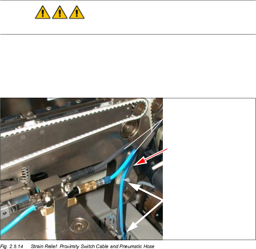
Å Using isopropyl alcohol, degrease the assembly surfaces for the mounting pedestal on the ver-
tical surface of the conveyor assembly (Fig. 2.5.14 -> 1) of each of the processing areas
.
Å In processing areas 2 and 3, degrease the surface for the mounting pedestal on the cable pit.
Å Mount the adhesive mounting pedestal.
.H\
1. Proximity switch cable and pneumatic hose
2. Cable and hose guide with strain relief device
3. 2 mounting pedestals, adhesive, with cable tie