00192299-02.pdf - 第96页
2 Retrofitting Instructions: Mechanical Ceramic Substrate Centering HS -50 SIPLACE HS -50 2.5 Sequence of Retrofitt ing 01/01 Issue 96 7 HVWLQJW KH3 OXJ,Q&RQQH FWLRQV $VVHPEOLQJWKH0DFKLQH Å As your fi …
SIPLACE HS-50 2 Retrofitting Instructions: Mechanical Ceramic Substrate Centering HS-50
01/01 Issue 2.5 Sequence of Retrofitting
95
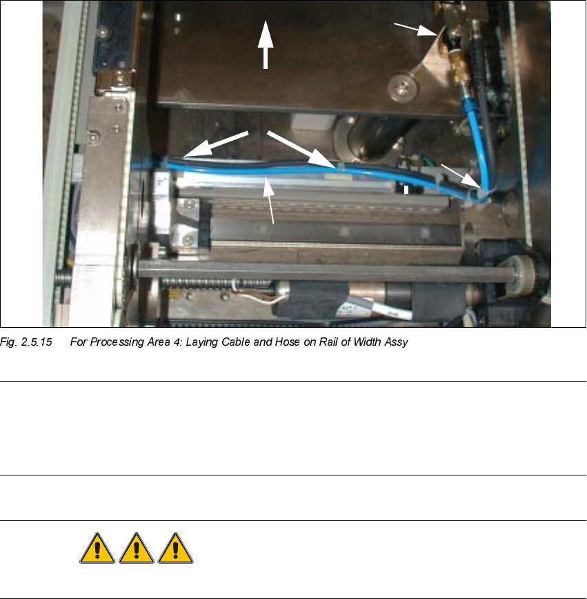
NOTE:
In processing areas 1 and 4 the cable and the pneumatic hose must be laid on the rail of the width
adjustment assy and fastened such that when the width adjustment assy is moved they do NOT
come into contact with it, causing them damage or tearing off the mounting pedestal.
DANGER
Do not perform the cleaning work with alcohol near an open flame.
Å Using isopropyl alcohol, remove the grease from the assembly surfaces for the mounting ped-
estal on the rail of the conveyor width adjustment assy:
– 2 mounting pedestals in conveyor 2, processing area 4 (see Fig. 2.5.15) and, in a like
manner,
– 1 mounting pedestal in conveyor 1, processing area 1, next to the fixed side of the conveyor.
Å In processing area 4 (see Fig. 2.5.7) mount two mounting pedestals on the top of the rail of the
conveyor width adjustment assy as shown in Fig. 2.5.15 and one mounting pedestal in pro-
cessing area 1.
Å Using cable ties, fasten the pneumatic hose and the proximity switch cable such that cable and
hose are close to the top of the rail. Resume work with the steps in Section 2.5.14.
Substrate
2 Retrofitting Instructions: Mechanical Ceramic Substrate Centering HS-50 SIPLACE HS-50
2.5 Sequence of Retrofitting 01/01 Issue
96
7HVWLQJW KH3 OXJ,Q&RQQH FWLRQV$VVHPEOLQJWKH0DFKLQH
Å As your final steps, make certain that the cables of the proximity switch and solenoid valves
are correctly allocated to the pertinent processing area.
Make certain that all plug-in connections and threaded hose couplings are firmly seated.
Å Remove all of the tools, etc., from the machine’s working area.
Å For changeover handling TSP 200: Install the cover on the conversion boards ("piggyback
boards") of the conveyor control in the machine frame.
Å For series handling TSP 200: Install the covers on the conversion boards in the pertinent PCB
conveyor.
Å Make certain that no cables or pneumatic hoses are pinched and place the covers back on all
of the cable pits in the PCB conveyor area and on the conveyor control in the machine frame.
Å Place the side panel of the machine frame against the top right of the machine (as the "theo-
retical pivot point") -> then move it to the machine frame at the right edge at bottom and further
move it to the machine frame. Then push it down all the way in the slots. Secure the side panel
(with a total of 6 screws).
Å Close the doors of the machine frame.
Å Where applicable, restore the plug-in connection of the movable component changeover table
and,
before docking the movable component changeover table, push the gantry until it is over the
PCB conveyor area. Then, after the compressed air is turned on - dock the component
changeover table.
Å Close the safety hoods.
Å 5HVXPHWKHZRUNZLWKWKHVWHSVLQ6HFWLRQ $FWLYDWLQJWKH2SW LRQ

SIPLACE HS-50 2 Retrofitting Instructions: Mechanical Ceramic Substrate Centering HS-50
01/01 Issue 2.6 Activating the Option
97
$FWLY DWLQJWKH2SWLRQ
2 Y H UY LHZ
The software version 502.xx is required in order to use the mechanical ceramic substrate center-
ing unit on the HS-50.
When the hardware of the option "mechanical ceramic substrate centering unit HS-50" is com-
pletely installed, the software automatically recognizes it on the HS-50 machine due to the cod-
ing plug (plug-in connection of the option to the conveyor control). Nevertheless, the option must
be activated in the SITEST program.
On the HS-50 the mechanical ceramic substrate centering unit is always combined with position
recognition of the fiducials on the substrate.
This position recognition is performed with the PCB camera with normal illumination or with the
optional oblique illumination. If the machine is already equipped with the multicolor PCB camera,
the fiducials are always centered with this camera. The optional oblique illumination is eliminated
in this case.
3OHDVHQRWH
– When the hardware of the mechanical ceramic substrate centering unit is installed, it MUST
also be ACTIVATED in the "Machine configuration" menu.
– Before the mechanical ceramic substrate centering unit in the "Machine configuration" menu
is deactivated, it MUST also be completely DEINSTALLED in BOTH processing areas of the
pertinent conveyor, i.e., the plug-in connections of the option must also be disconnected first.
In parallel to this, the conveyor assemblies must be changed over to transport PCBs.
DANGER
During the following work, pay attention to the DANGER text regarding work with the SITEST pro-
gram in Section 2.2