00193356-02.pdf - 第32页
2 Assembly Instructions: Component Sensor (Opti on) for RV12-DLM1 Placement Head SIPLACE S-25 HM 2.5 Assembly Kit, Documentation, Tools, etc. 04/2007 Edition 32 2.5 Assembly Kit, Document ation, T ools, etc. 2.5.1 Assemb…
SIPLACE S-25 HM 2 Assembly Instructions: Component Sensor (Option) for RV12-DLM1 Placement Head
04/2007 Edition 2.4 Safety Instructions
31
2.4.2 Definitions
DANGER
in terms of these instructions means that death, severe bodily injury or considerable material da-
mage WILL occur if the instructions about danger are not followed.
2
WARNING
in terms of these instructions means that death, severe bodily injury or considerable material da-
mage may occur if the warnings are not heeded. 2
CAUTION
in terms of these instructions mean that minor bodily injury or material may occur if the cautions
are not heeded. 2
NOTE
in terms of these instructions is a statement of important information about the product or the
pertinent portion of the instructions to which particular attention is being drawn. 2

2 Assembly Instructions: Component Sensor (Option) for RV12-DLM1 Placement Head SIPLACE S-25 HM
2.5 Assembly Kit, Documentation, Tools, etc. 04/2007 Edition
32
2.5 Assembly Kit, Documentation, Tools, etc.
2.5.1 Assembly Kit for Component Sensor for 12-Segment C+P
(RV12-DLM1), Item no.: 00118021-01
2.5.2 Assembly Kits for SW 503.xx
2.5.3 Assembly Kits for "Modular Head PCB" on HS-50 and S-25 HM
If there is not as yet a modular head PCB on the machine to be assemblied, you need one of the
following assembly kits, each of which contains the pertinent parts for all of the machine’s: 2
2.5.4 Additional Documents Required
-
If applicable, SITEST Software Instructions, V 5.03.xx, Item no.:00193330-01 (G + E)
Qnty.
Designation Item no.:
1
Component sensor assembly SP-12 (incl. cable with connector*) 00367142-01
1
2 socket hex head cap screws M 3 x 12 *)
1
1 socket hex head cap screws M 3 x 14 *)
1
Assembling gauge for component sensor *) 03003110-01
1
Assembly Instructions for Component Sensor
S-25 HM and HS-50
00193356-01
1
Manual for the Placement of 0201 Components, G + E 00191667-04
*) see Fig. 1.5.1
Qnty.
Designation Item no.:
1
Line computer SW 503/1
(Documentation and CD, German and English)
or
00368385-01
1
Line computer SW SIPLACE PRO 1.3 on request
1
SW SIPLACE station 503/1
(Documentation and CD, German and English)
00368293-01
1
Language pack:
CD with GUI and documentation
00368802-01
Qnty.
Designation Item no.:
1
Assembly kit "PCB HS-50" head (modular) 00359489-01 *)
1
Assembly kit "PCB S-23 head (S-25 HM)", modular 00359488-01 *)
*) The assembly instructions "Modular Head PCBs on S-23, S-25 HM, F5 HM,
HS-50" (item no.: 00192393-01, G + E) is included in the assembly kit.
SIPLACE S-25 HM 2 Assembly Instructions: Component Sensor (Option) for RV12-DLM1 Placement Head
04/2007 Edition 2.5 Assembly Kit, Documentation, Tools, etc.
33
2.5.5 Tools, Expendable Materials
– Allen wrench, size 2.5 and oblique-nosed cutting pliers
– Torque wrench (see table below)
– Per placement head: 2 cable ties LxW = 140 x 3.6 mm Item no.: 00805141-01
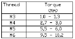
2.5.6 Torques for Screws
Setting the correct torque prevents parts (component sensor, blast air unit) from being loosened
by the travel movement of the gantry.