00193356-02.pdf - 第31页
SIPLACE S-25 HM 2 Assembly Instructions: Component Sensor (Option) for RV12-DLM1 Placement Head 04/2007 Edition 2.4 Safety Instructions 31 2.4.2 Definitions DANGER in terms of these inst ructions me ans that deat h, seve…
2 Assembly Instructions: Component Sensor (Option) for RV12-DLM1 Placement Head SIPLACE S-25 HM
2.4 Safety Instructions 04/2007 Edition
30
2.4.1 Safety Instructions for Laser Radiation
CAUTION
The component sensor is in accordance with Laser Class 1 when it is properly installed in the ma-
chine and is in undamaged condition. The light beam is spatially limited on the receiver side. 2
With this laser class, no laser warning signs are required on the machine (on the safety hoods) or
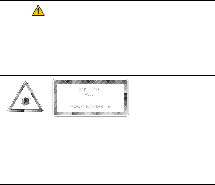
on the component sensor itself. It is sufficient if the signs identifying the laser class "1" in the
User Manual, as shown below.
Abb. 2.4.1 Laser Warning Signs in the User Manual in the Pertinent Language
If the component sensor is damaged or manipulated, it is not permissible to install/continue ope-
rating it. The component sensor is operated with +5 V and is not integrated into the safety circuit.
Rules for Germany:
Observe the guidelines of the Main Association of the German Trade Association, VBG 93.
In all other countries, comply with the pertinent guidelines and standards of the specific countries
in question. Standards to be observed: IEC 60825-1, EN 60825-1.
2
SIPLACE S-25 HM 2 Assembly Instructions: Component Sensor (Option) for RV12-DLM1 Placement Head
04/2007 Edition 2.4 Safety Instructions
31
2.4.2 Definitions
DANGER
in terms of these instructions means that death, severe bodily injury or considerable material da-
mage WILL occur if the instructions about danger are not followed.
2
WARNING
in terms of these instructions means that death, severe bodily injury or considerable material da-
mage may occur if the warnings are not heeded. 2
CAUTION
in terms of these instructions mean that minor bodily injury or material may occur if the cautions
are not heeded. 2
NOTE
in terms of these instructions is a statement of important information about the product or the
pertinent portion of the instructions to which particular attention is being drawn. 2

2 Assembly Instructions: Component Sensor (Option) for RV12-DLM1 Placement Head SIPLACE S-25 HM
2.5 Assembly Kit, Documentation, Tools, etc. 04/2007 Edition
32
2.5 Assembly Kit, Documentation, Tools, etc.
2.5.1 Assembly Kit for Component Sensor for 12-Segment C+P
(RV12-DLM1), Item no.: 00118021-01
2.5.2 Assembly Kits for SW 503.xx
2.5.3 Assembly Kits for "Modular Head PCB" on HS-50 and S-25 HM
If there is not as yet a modular head PCB on the machine to be assemblied, you need one of the
following assembly kits, each of which contains the pertinent parts for all of the machine’s: 2
2.5.4 Additional Documents Required
-
If applicable, SITEST Software Instructions, V 5.03.xx, Item no.:00193330-01 (G + E)
Qnty.
Designation Item no.:
1
Component sensor assembly SP-12 (incl. cable with connector*) 00367142-01
1
2 socket hex head cap screws M 3 x 12 *)
1
1 socket hex head cap screws M 3 x 14 *)
1
Assembling gauge for component sensor *) 03003110-01
1
Assembly Instructions for Component Sensor
S-25 HM and HS-50
00193356-01
1
Manual for the Placement of 0201 Components, G + E 00191667-04
*) see Fig. 1.5.1
Qnty.
Designation Item no.:
1
Line computer SW 503/1
(Documentation and CD, German and English)
or
00368385-01
1
Line computer SW SIPLACE PRO 1.3 on request
1
SW SIPLACE station 503/1
(Documentation and CD, German and English)
00368293-01
1
Language pack:
CD with GUI and documentation
00368802-01
Qnty.
Designation Item no.:
1
Assembly kit "PCB HS-50" head (modular) 00359489-01 *)
1
Assembly kit "PCB S-23 head (S-25 HM)", modular 00359488-01 *)
*) The assembly instructions "Modular Head PCBs on S-23, S-25 HM, F5 HM,
HS-50" (item no.: 00192393-01, G + E) is included in the assembly kit.